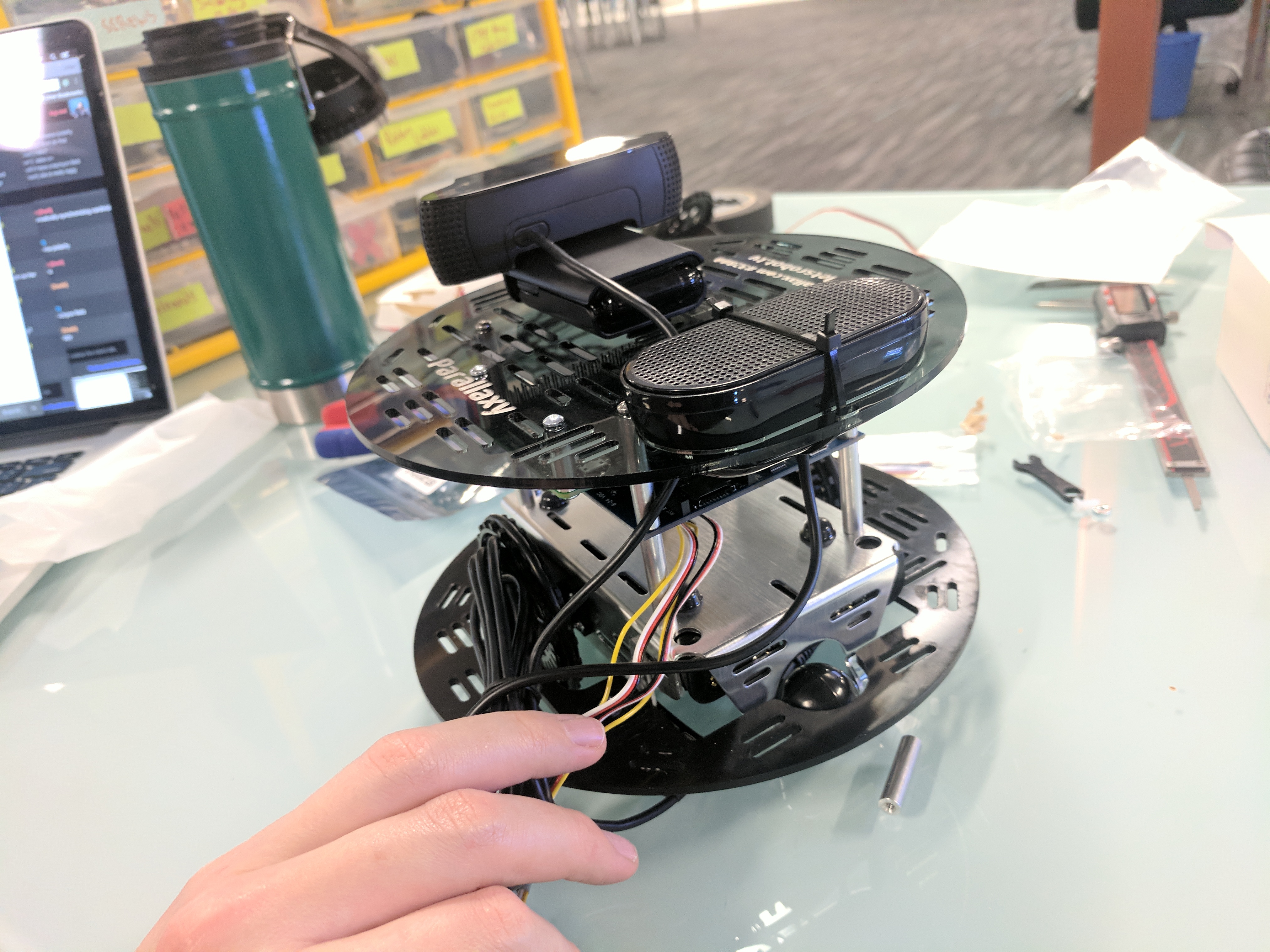
Official Parallaxy Robot
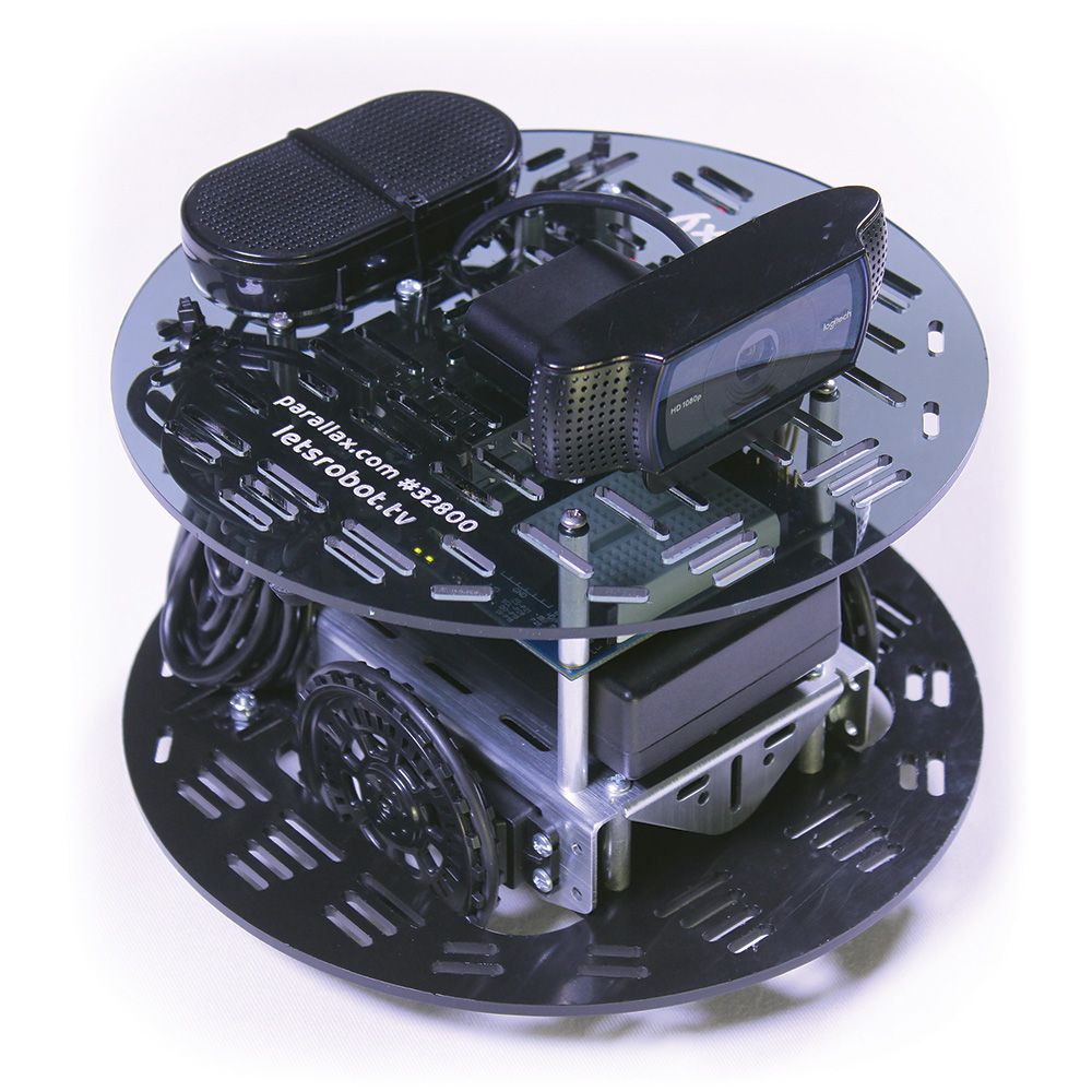
Announcing the new exclusive Parallaxy Kit from Parallax Inc. made for Remo.TV!
You can purchase it from their website, https://www.parallax.com/product/32800
This is the perfect kit for a first robot. It comes with everything you need and there is no need for specialized tools like a soldering iron or multimeter.
Build Parallaxy
Make sure all Activity Board WX servo ports are set to
5V, and if not, move them. The pins markedVINshould be left bare.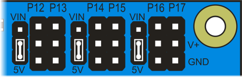
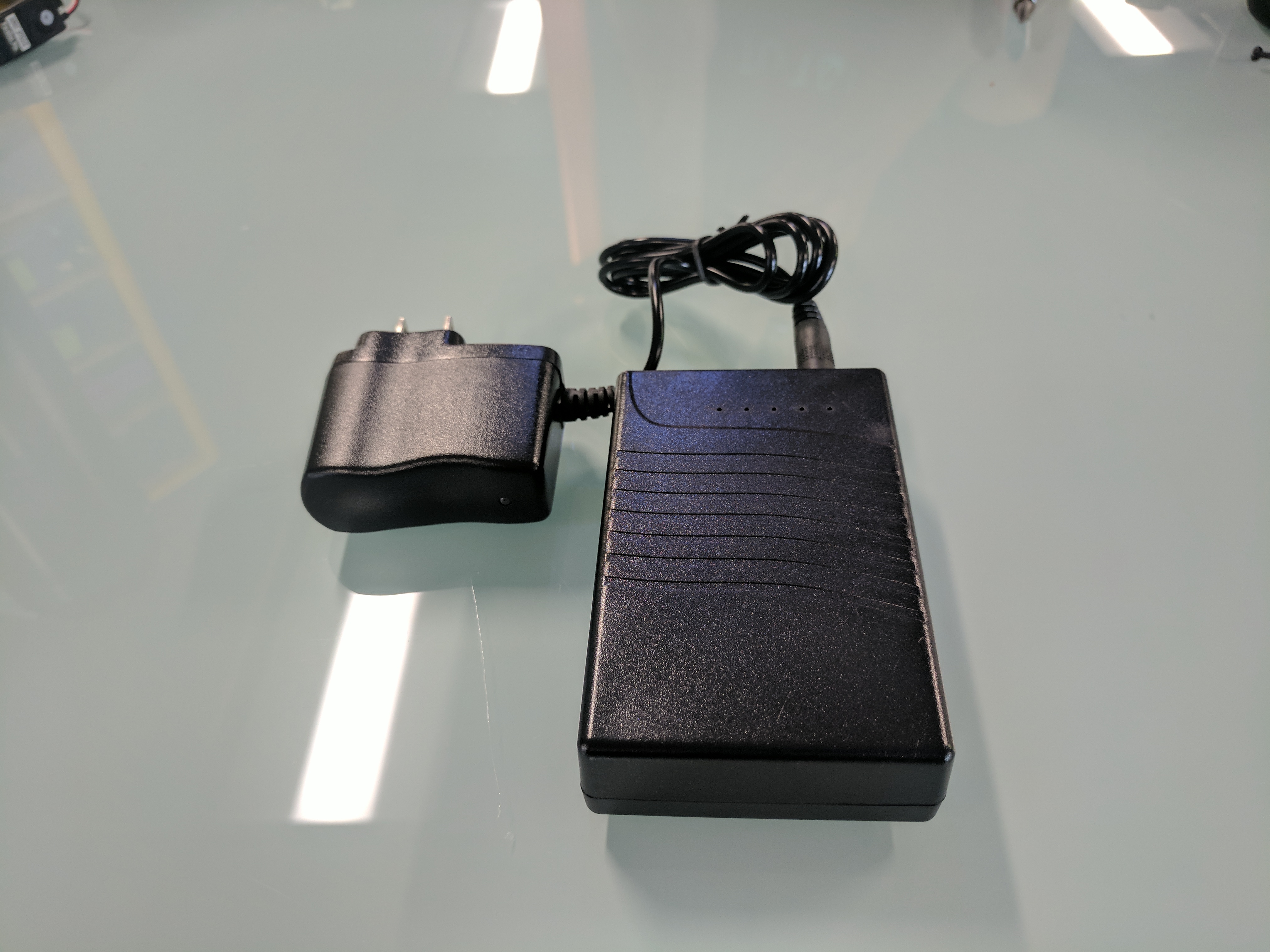
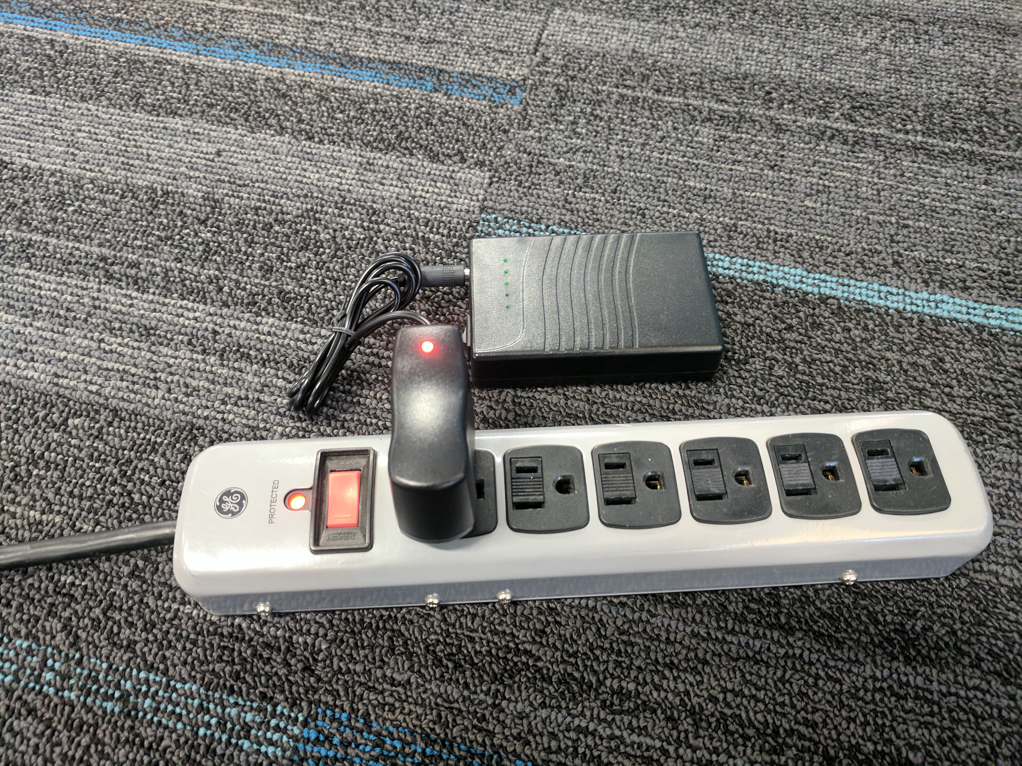
Charge the battery brick according to its manufacturer instructions.
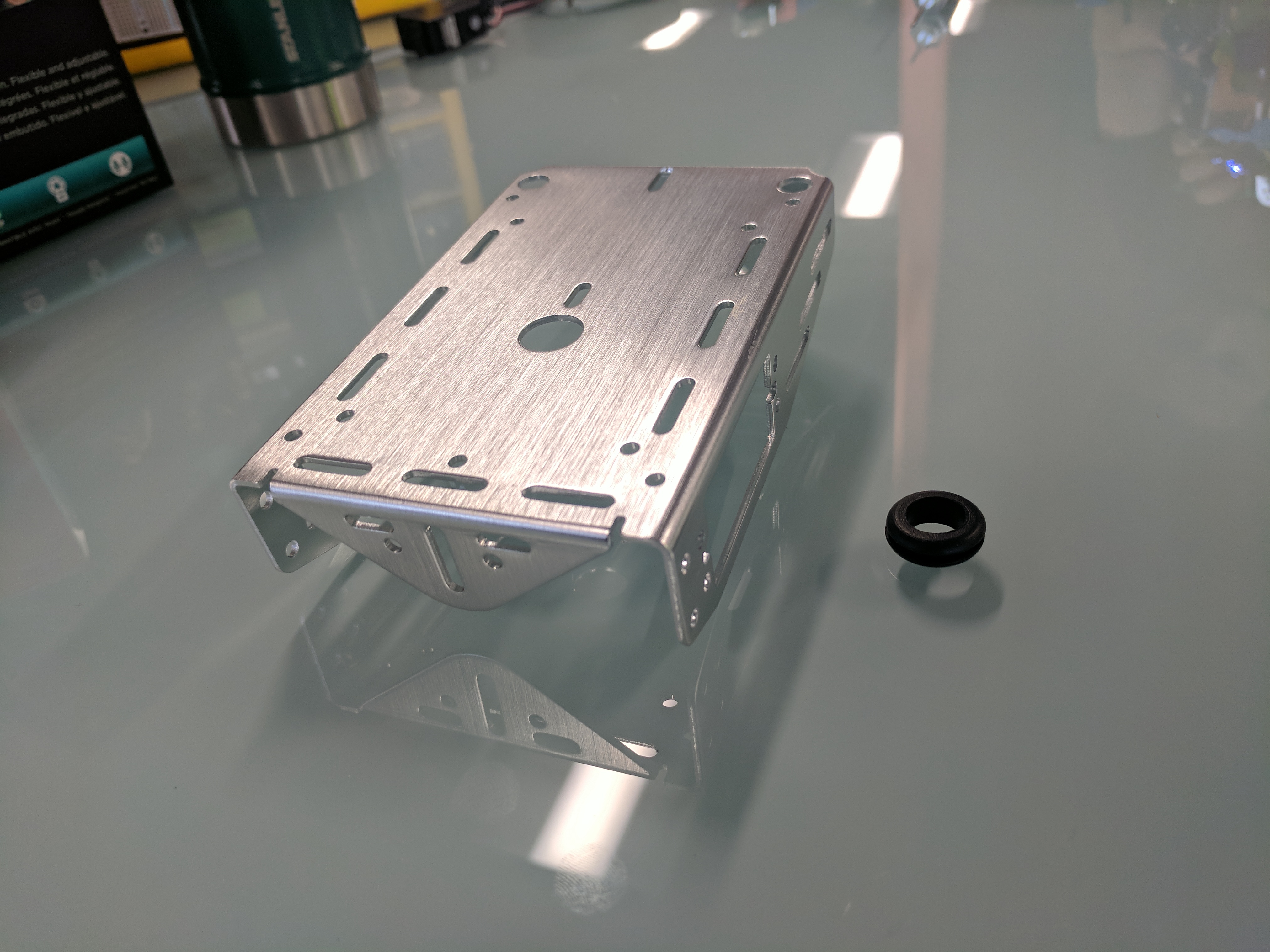
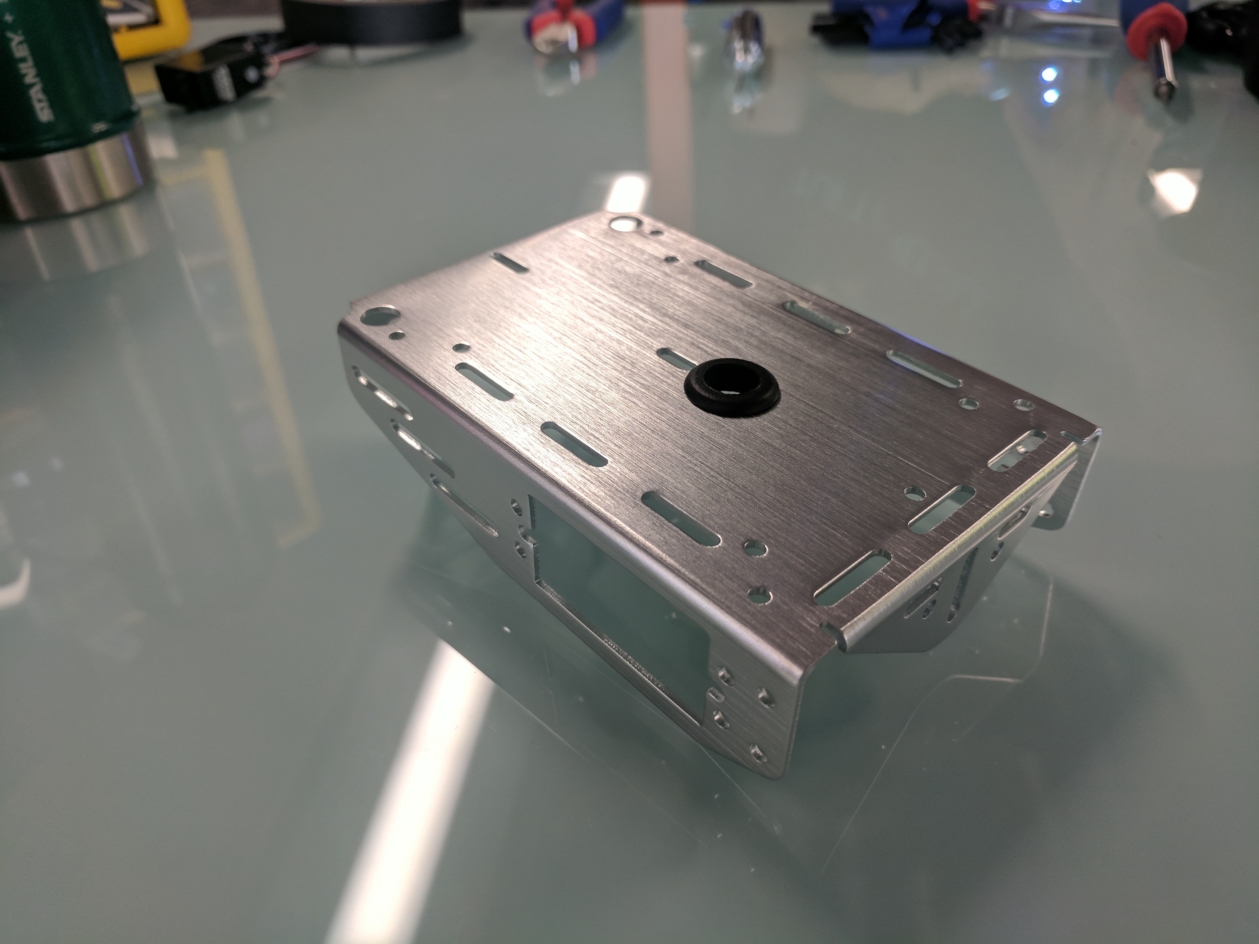
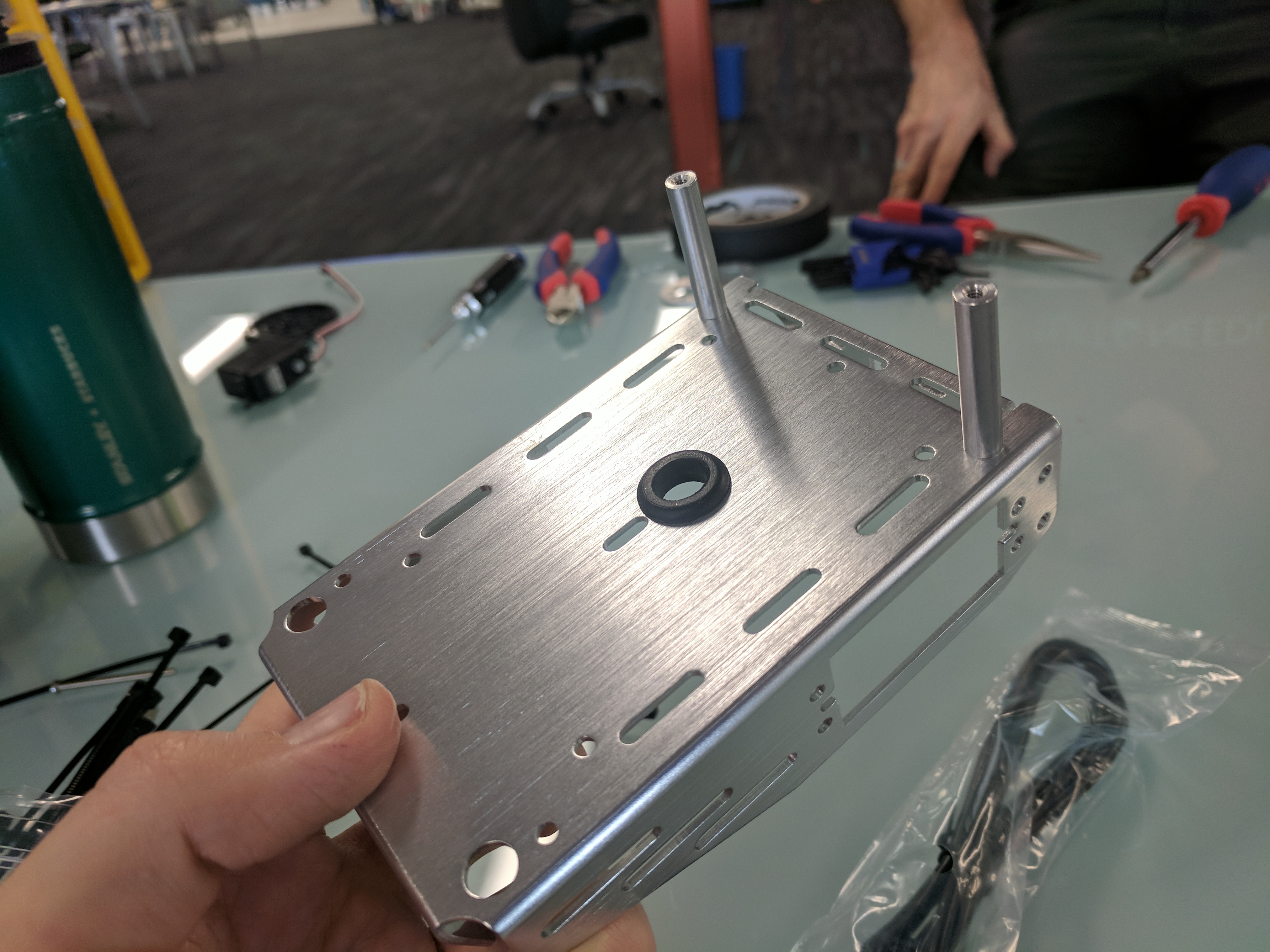
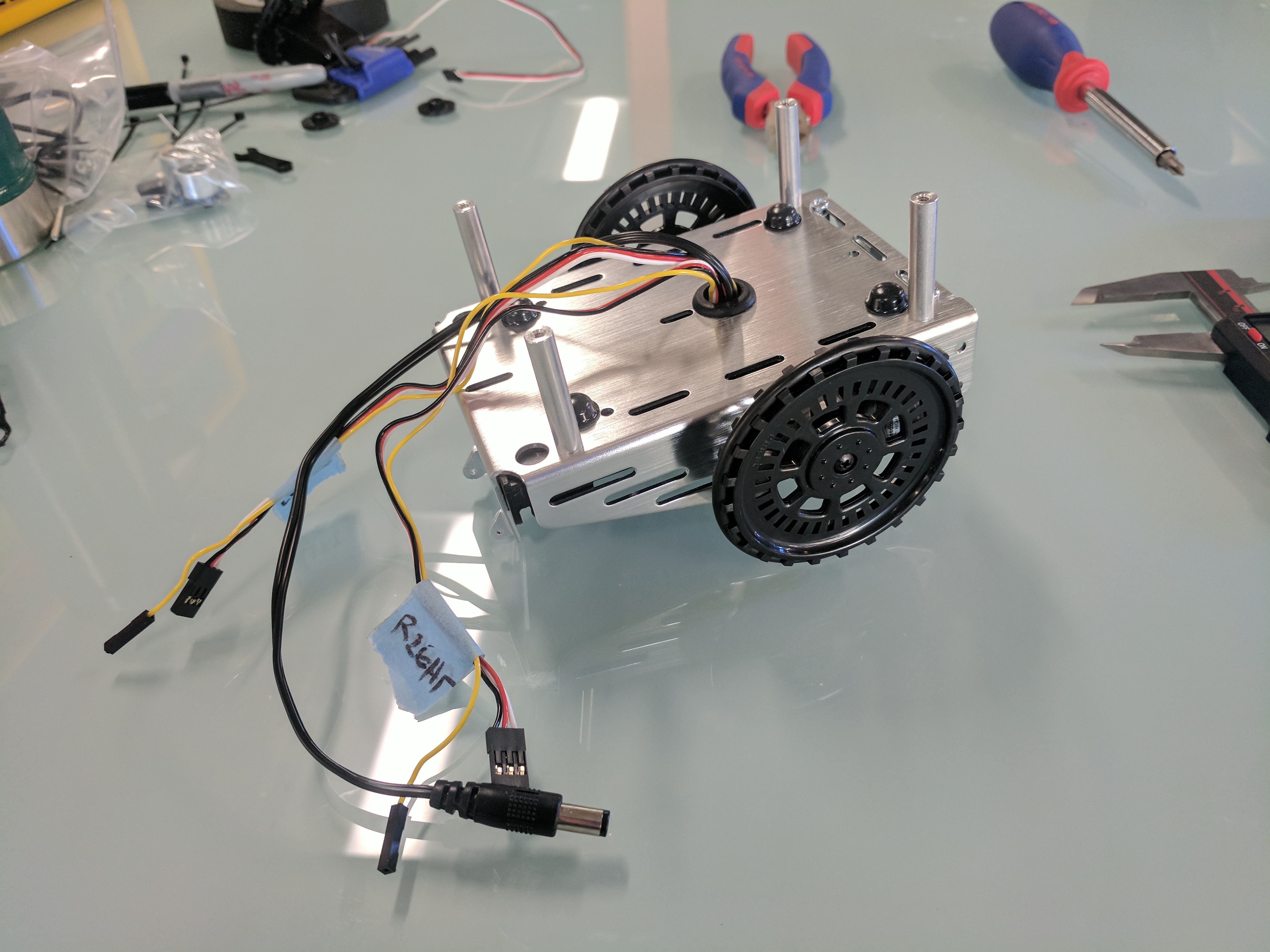
Seat the rubber grommet into the chassis center hole - the metal edge of the hole will fit in the groove of the grommet.
Attach two 1¼” threaded standoffs to the top of the chassis with ⅜” panhead steel screws, using outermost corner holes farthest away from the curved tail wheel mount.
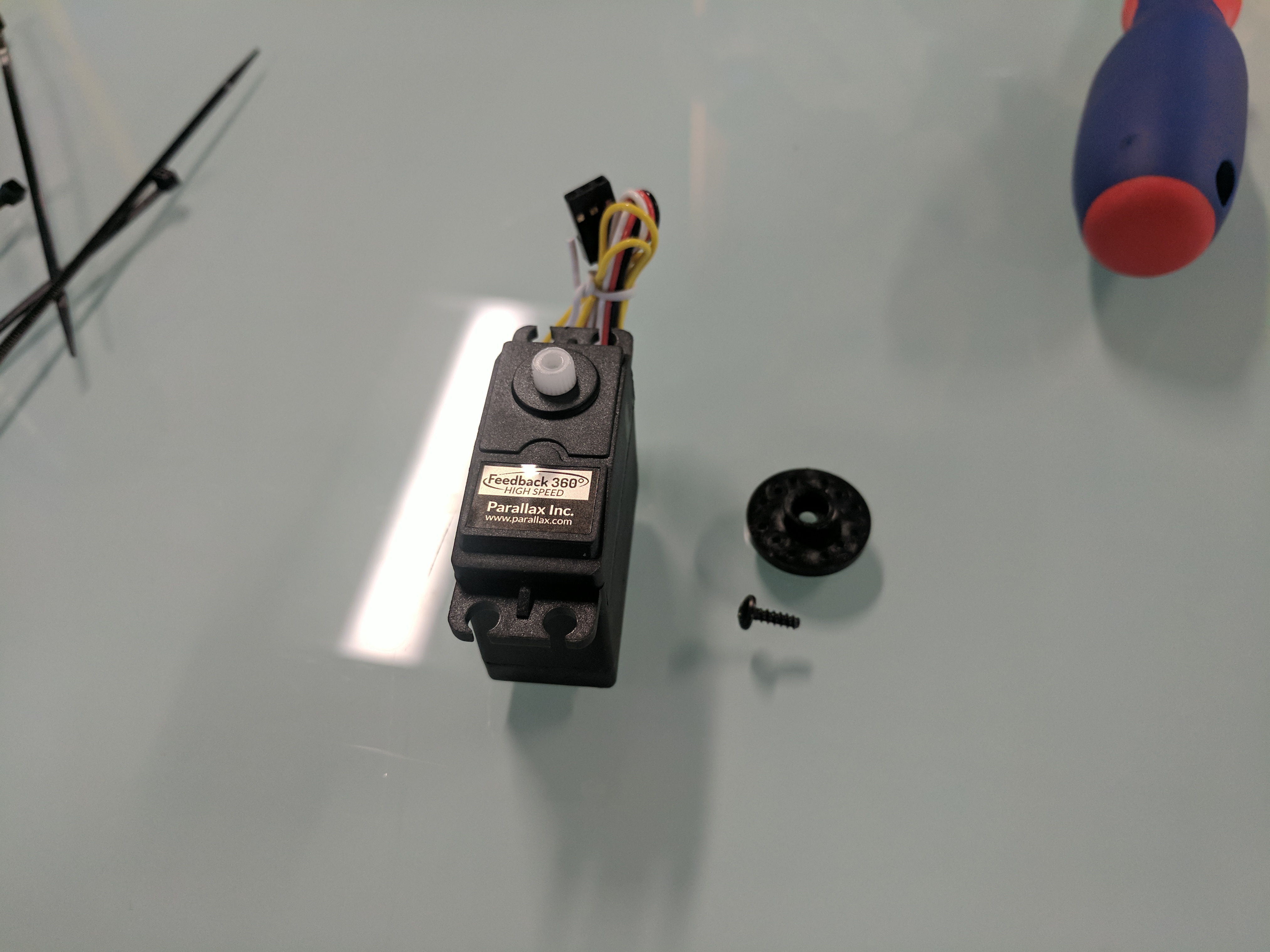
Take the servo horns off the servos, and SAVE THE SCREWS!
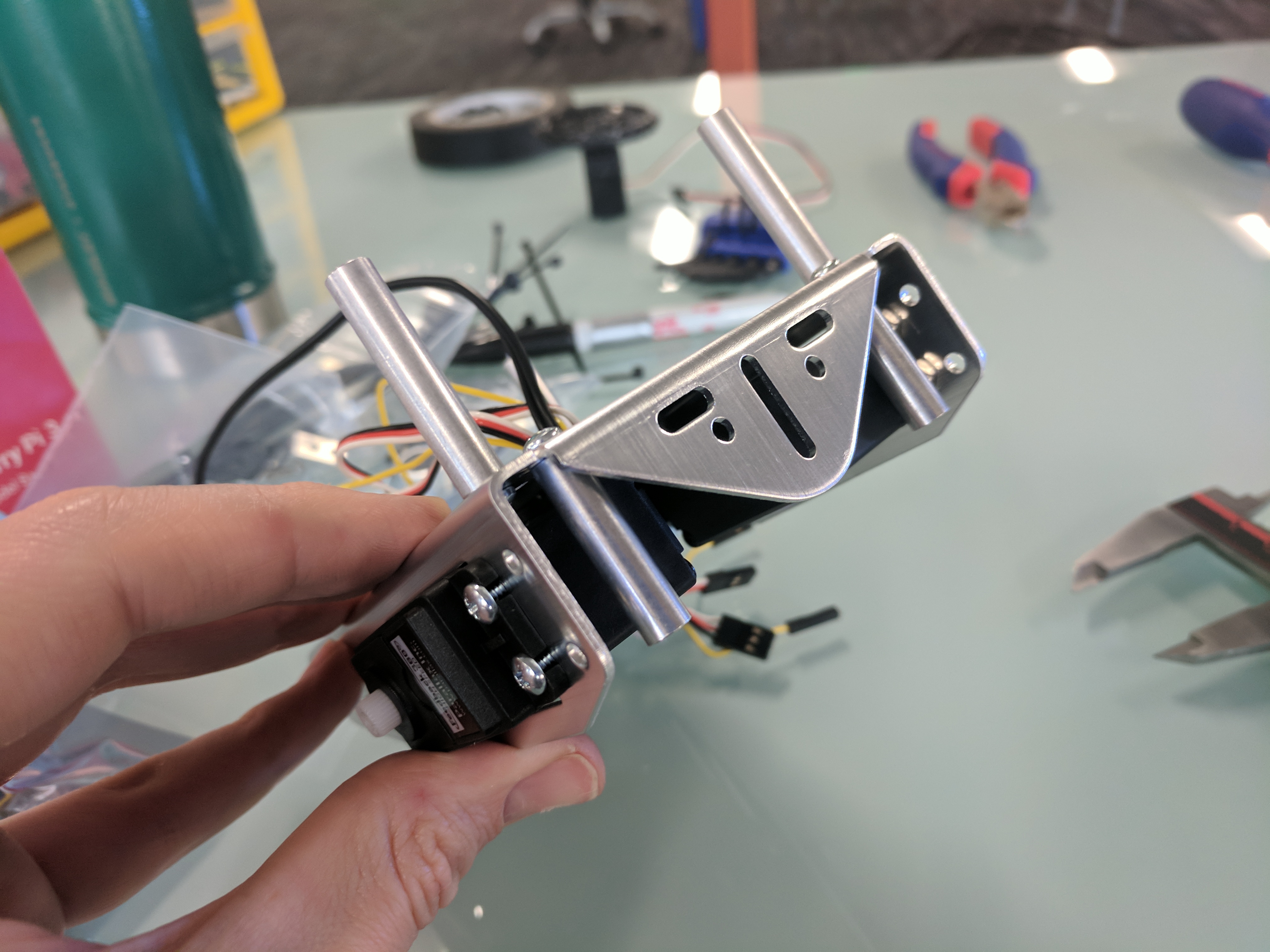
Insert a servo into the chassis from the outside, with its cables trailing toward the grommet hole.
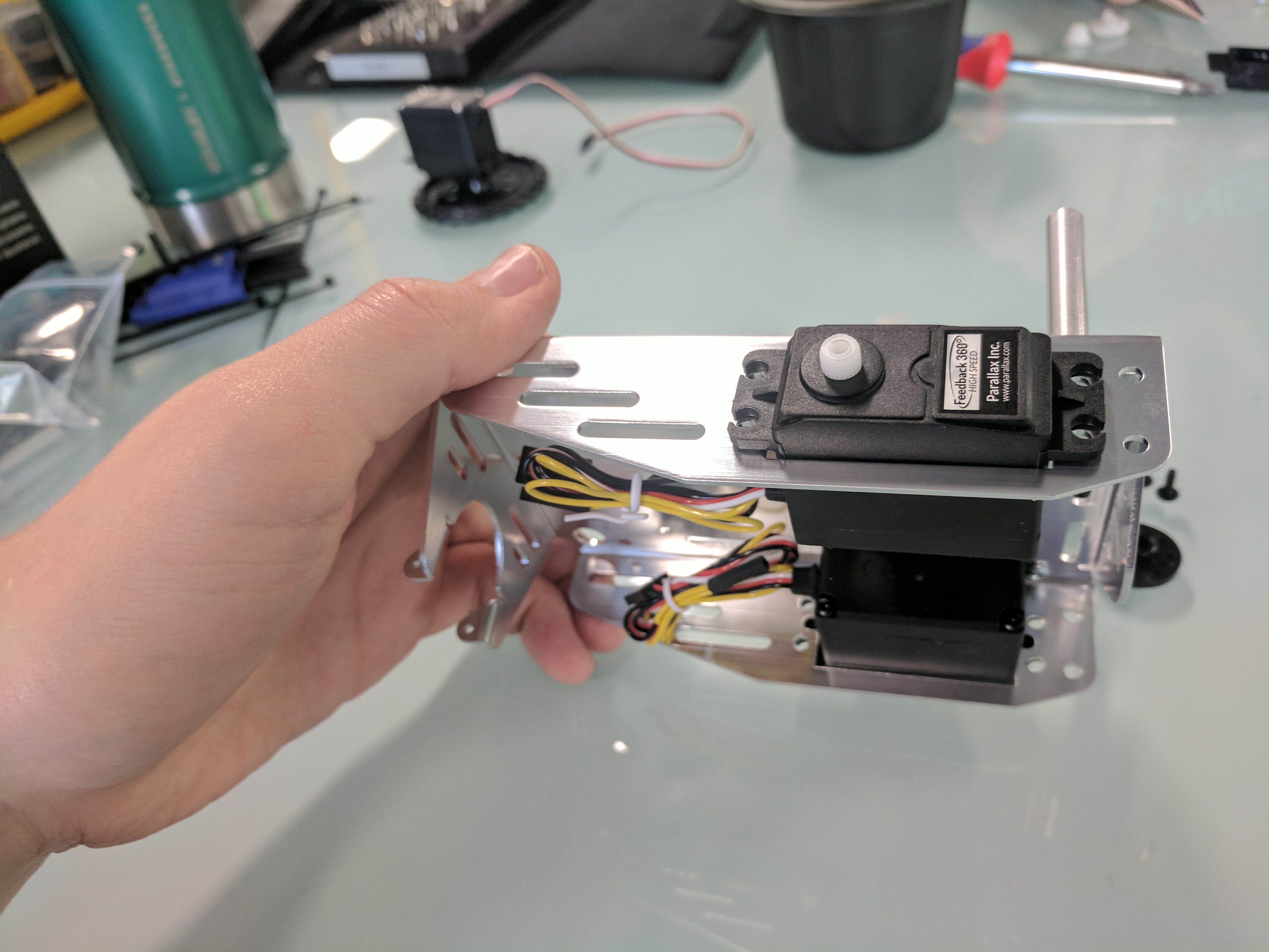
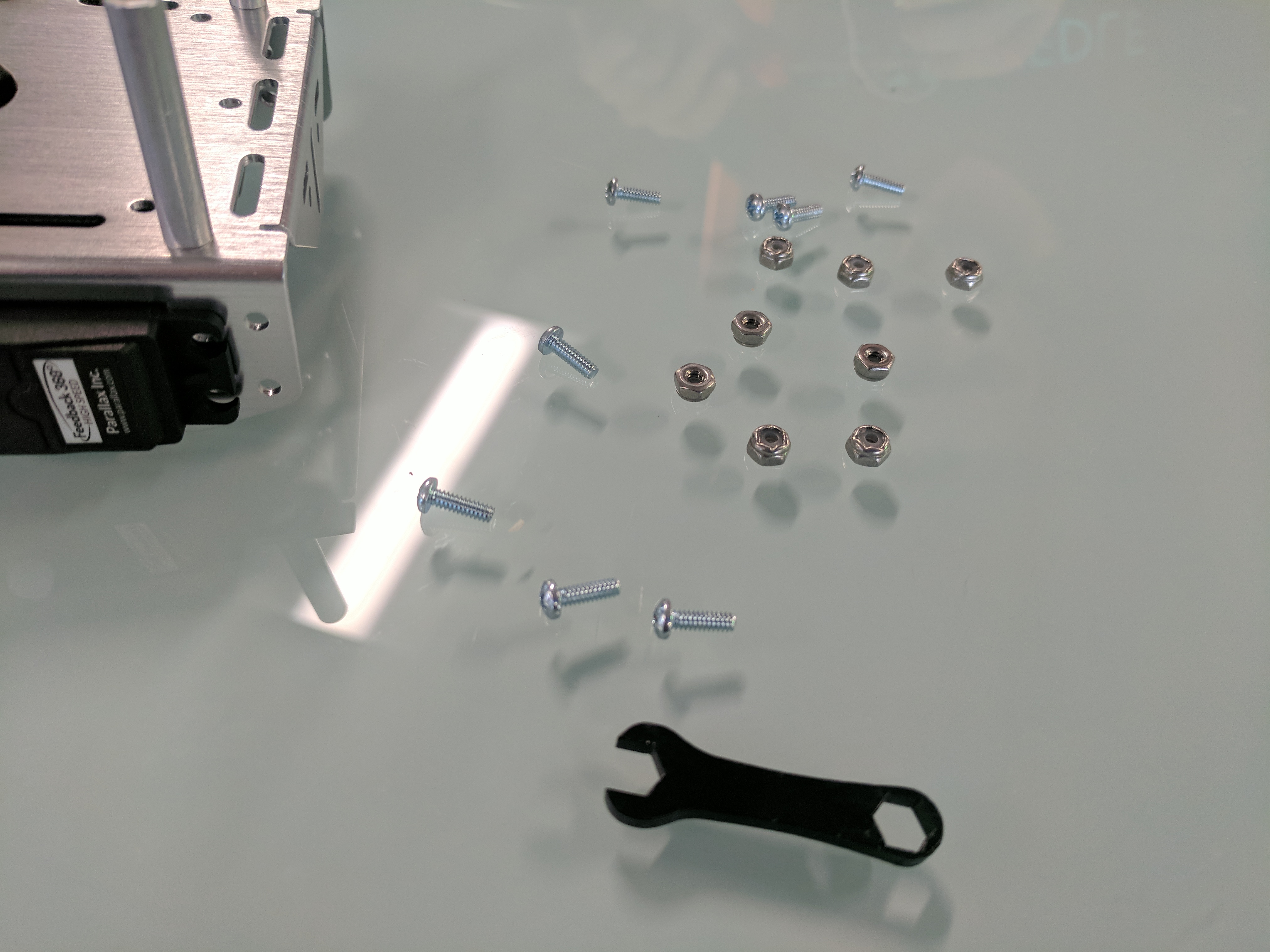
Secure the servo to the chassis with four ⅜” screws and four Nylon-core lock-nuts. Repeat with the other servo.
Tip
Press the closed end of the little black wrench firmly over a lock-nut to pick it up and hold it while working.
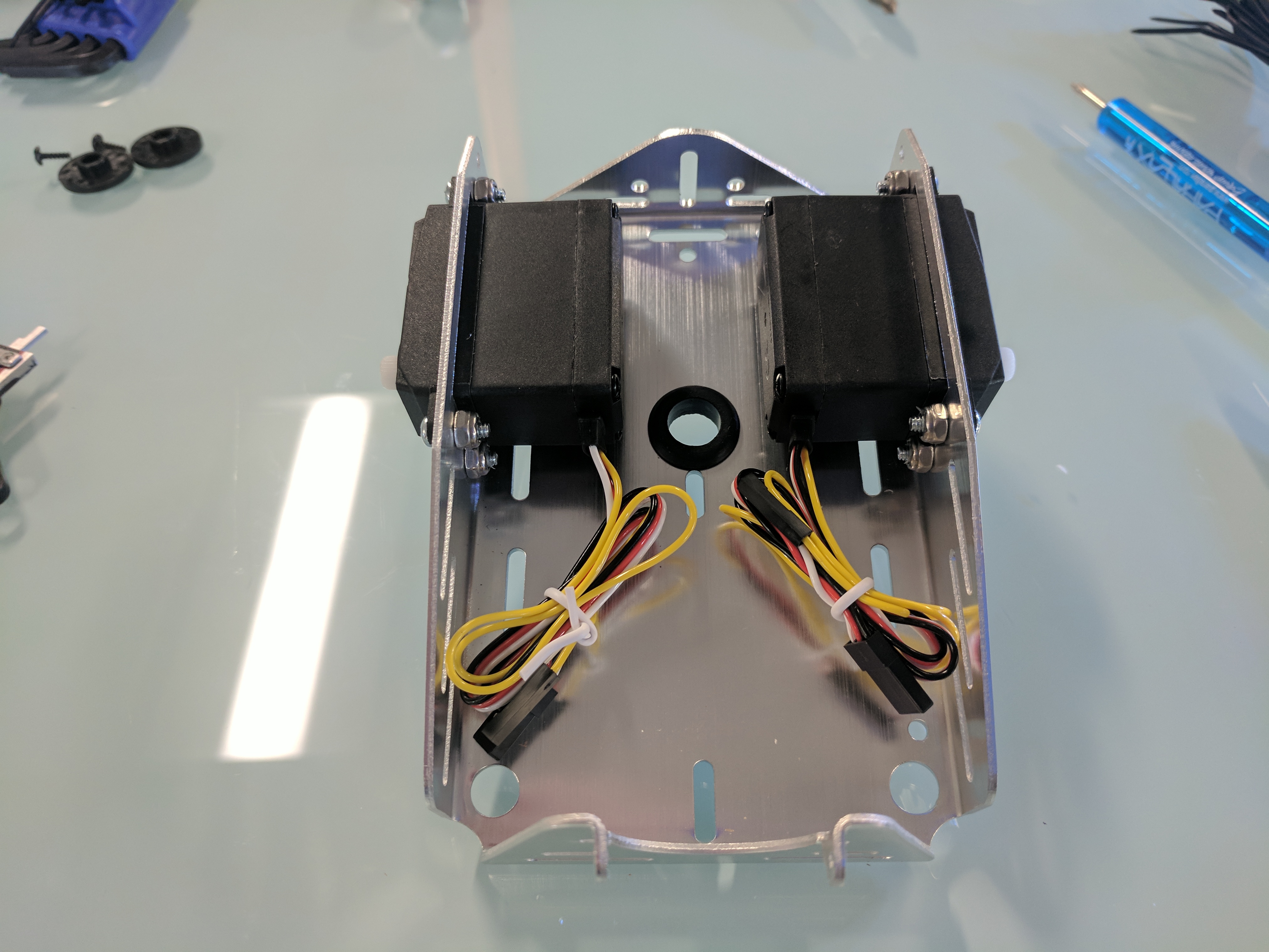
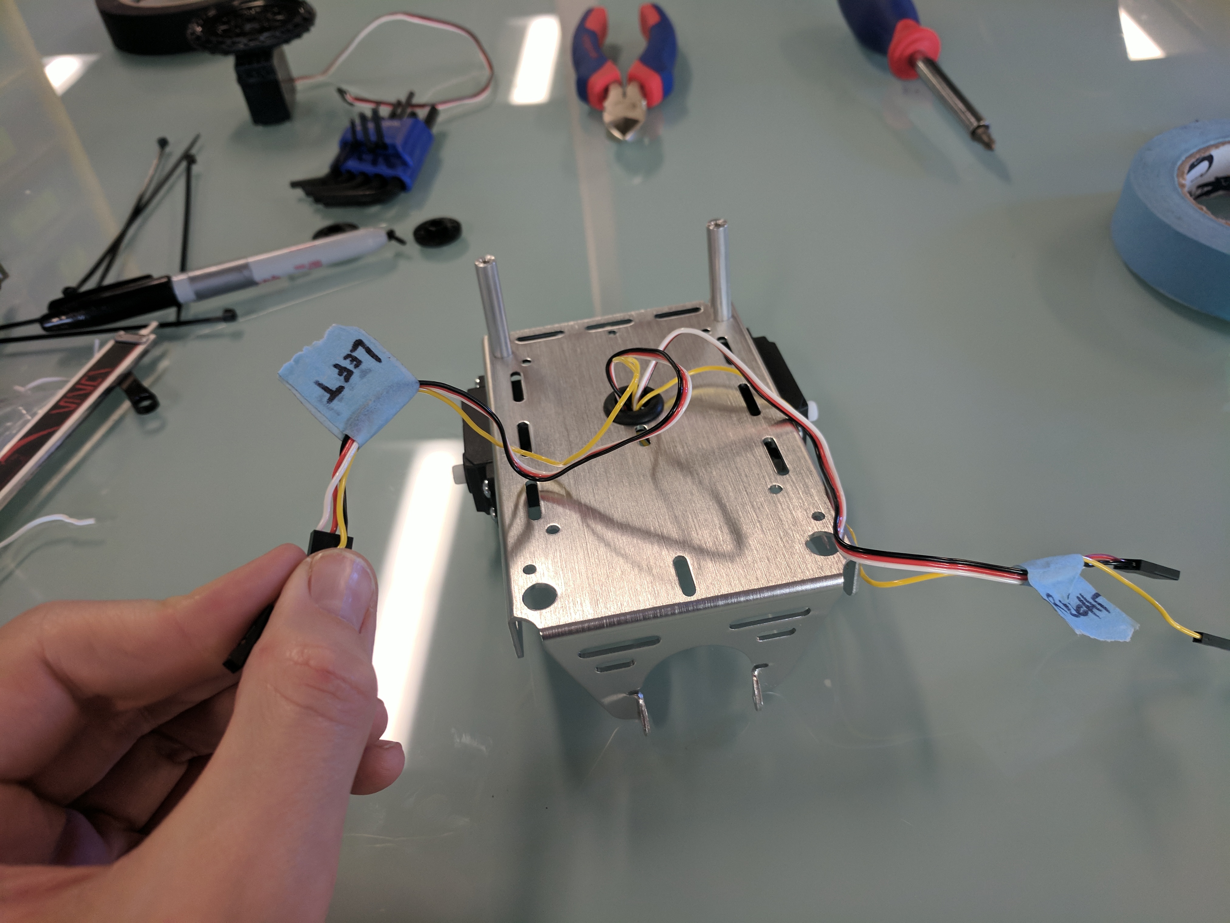
Thread all of the servo cables through the grommet hole to the top of the chassis.
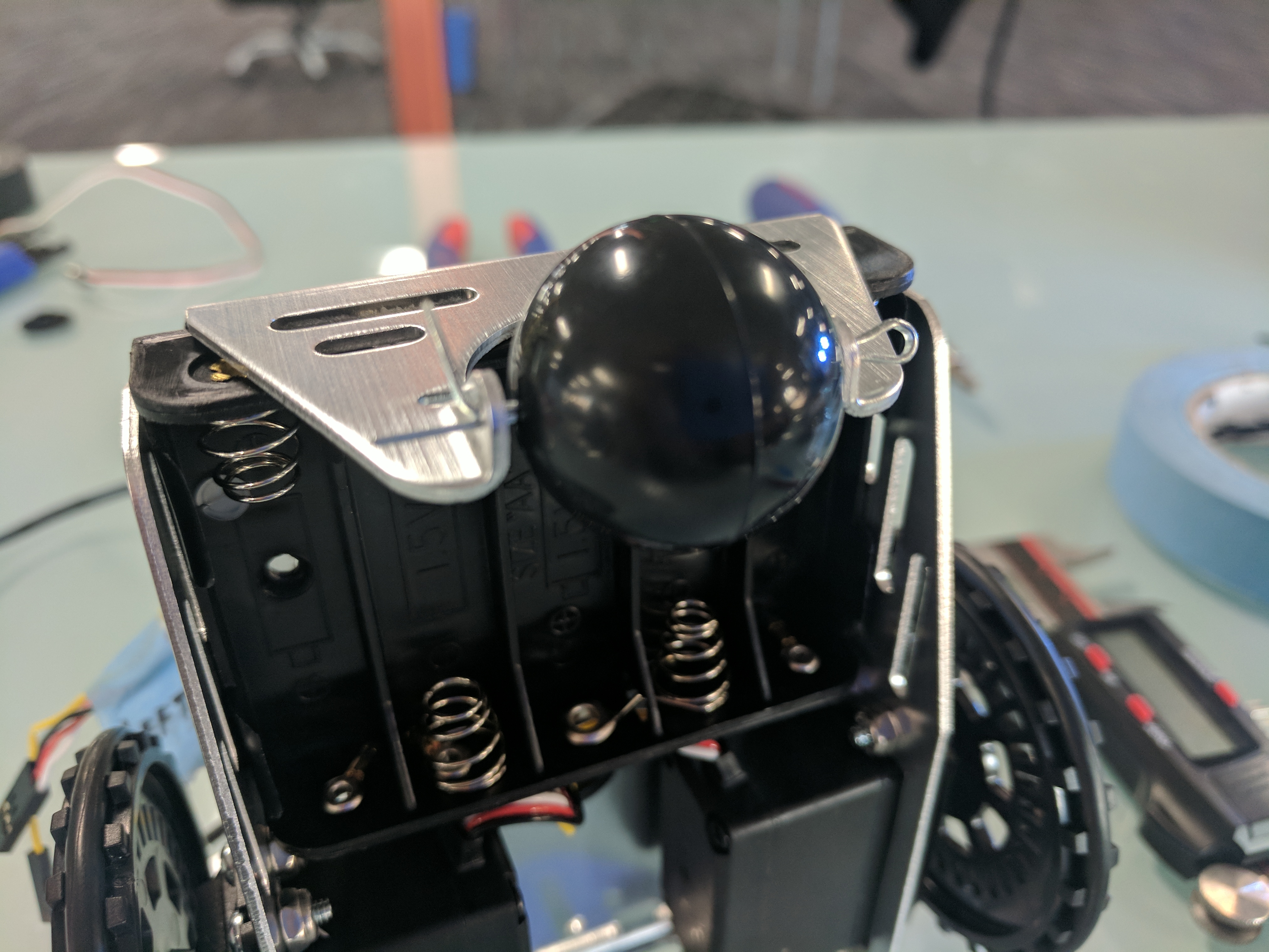
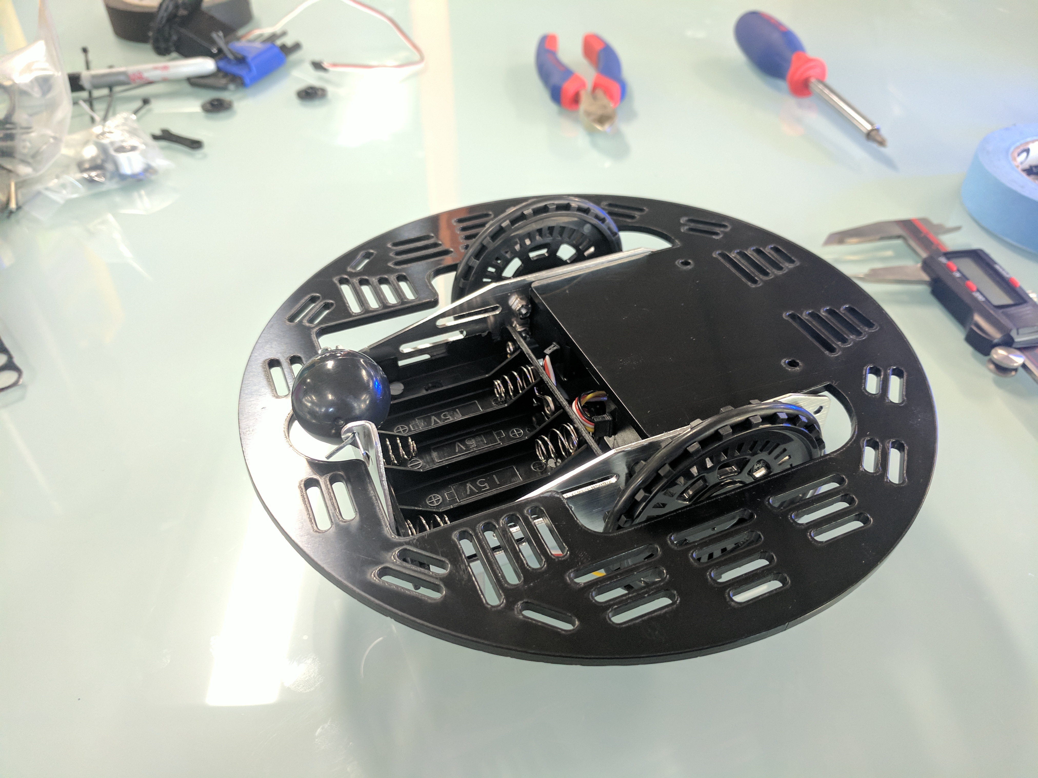
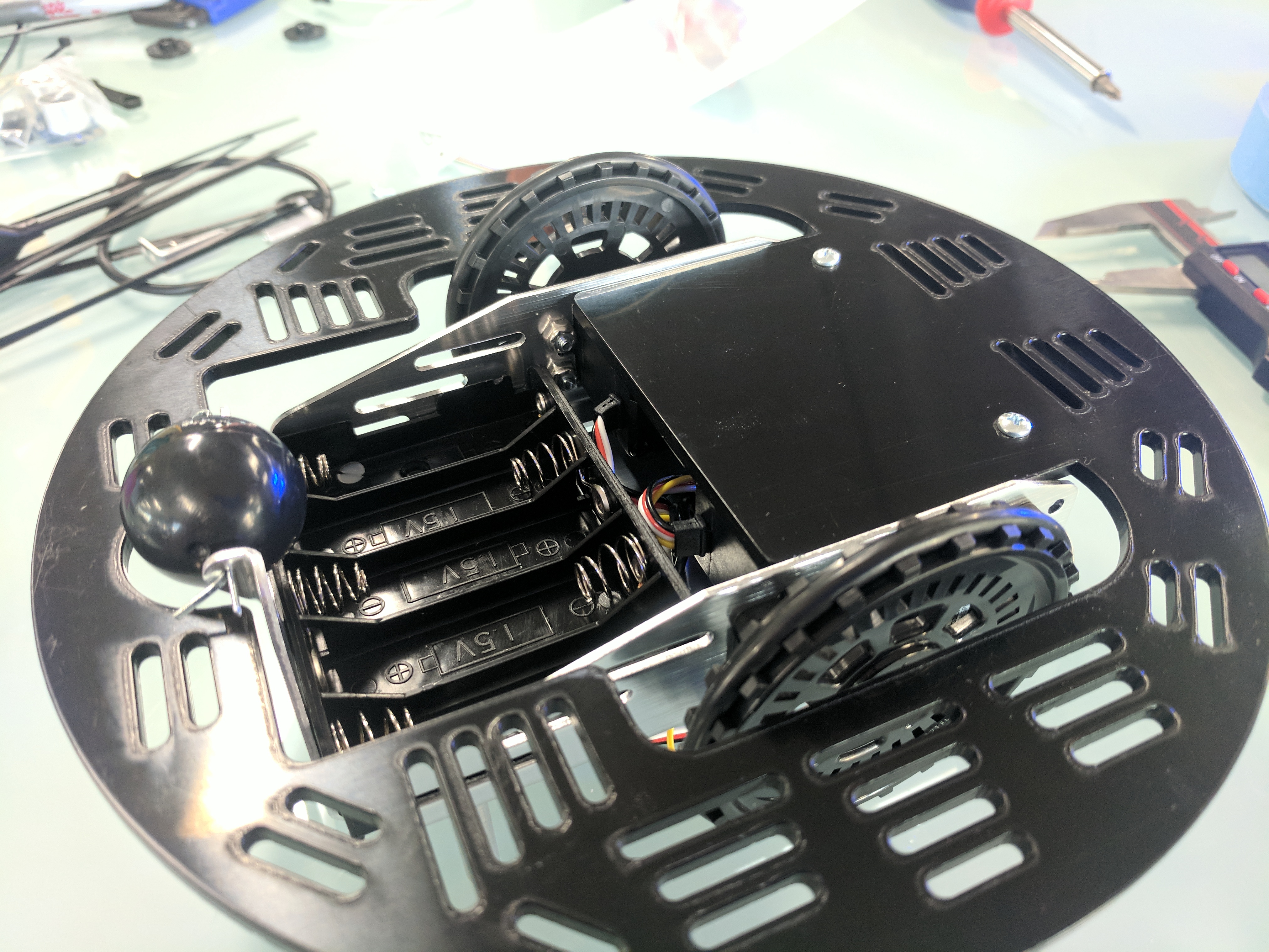
OPTIONAL - If adding the 5-AA battery pack for optional future use, insert it under the chassis with its cable toward the grommet hole. It will snap in place with a little pressure.
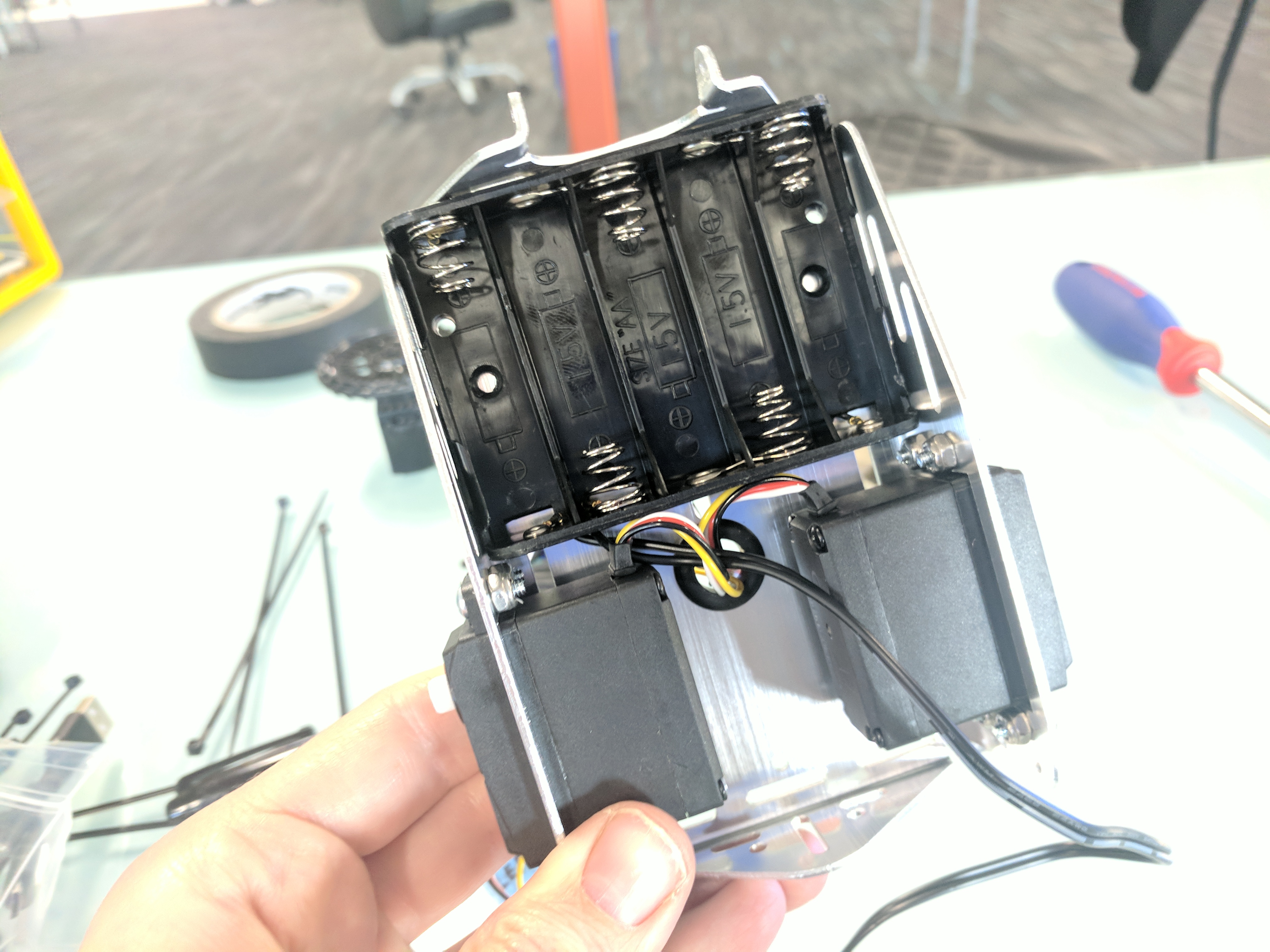
Attach two more threaded standoffs to the top of the chassis using the two remaining outermost small holes, with Nylon flat-head screws. Thread right through the plastic 5-AA battery pack if using it (Nylon screws won’t nick and possibly short the batteries). Tighten gently.
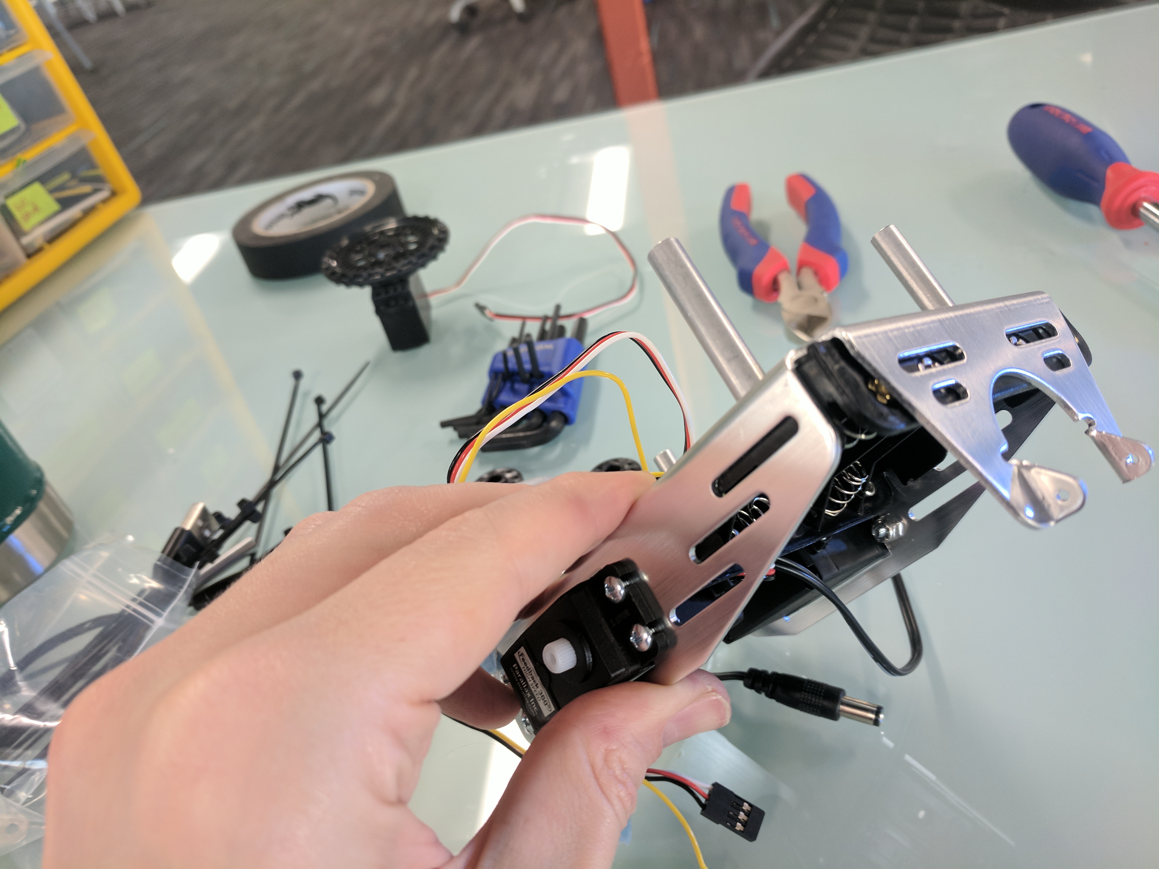
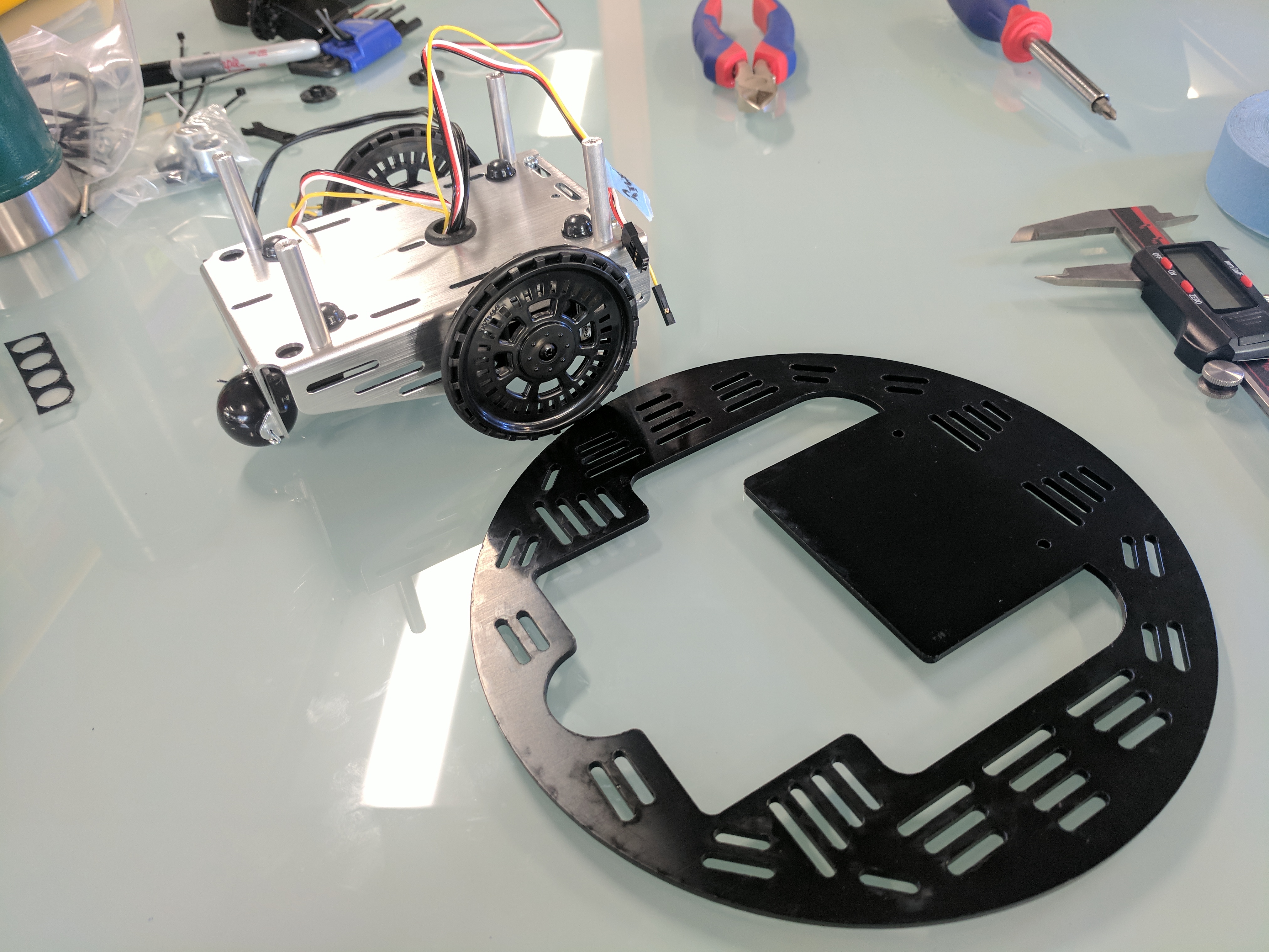
Attach a 1” threaded standoff to each of the two outermost slots in the bottom front of the chassis (in front of the servos) and secure with ¼” screws.
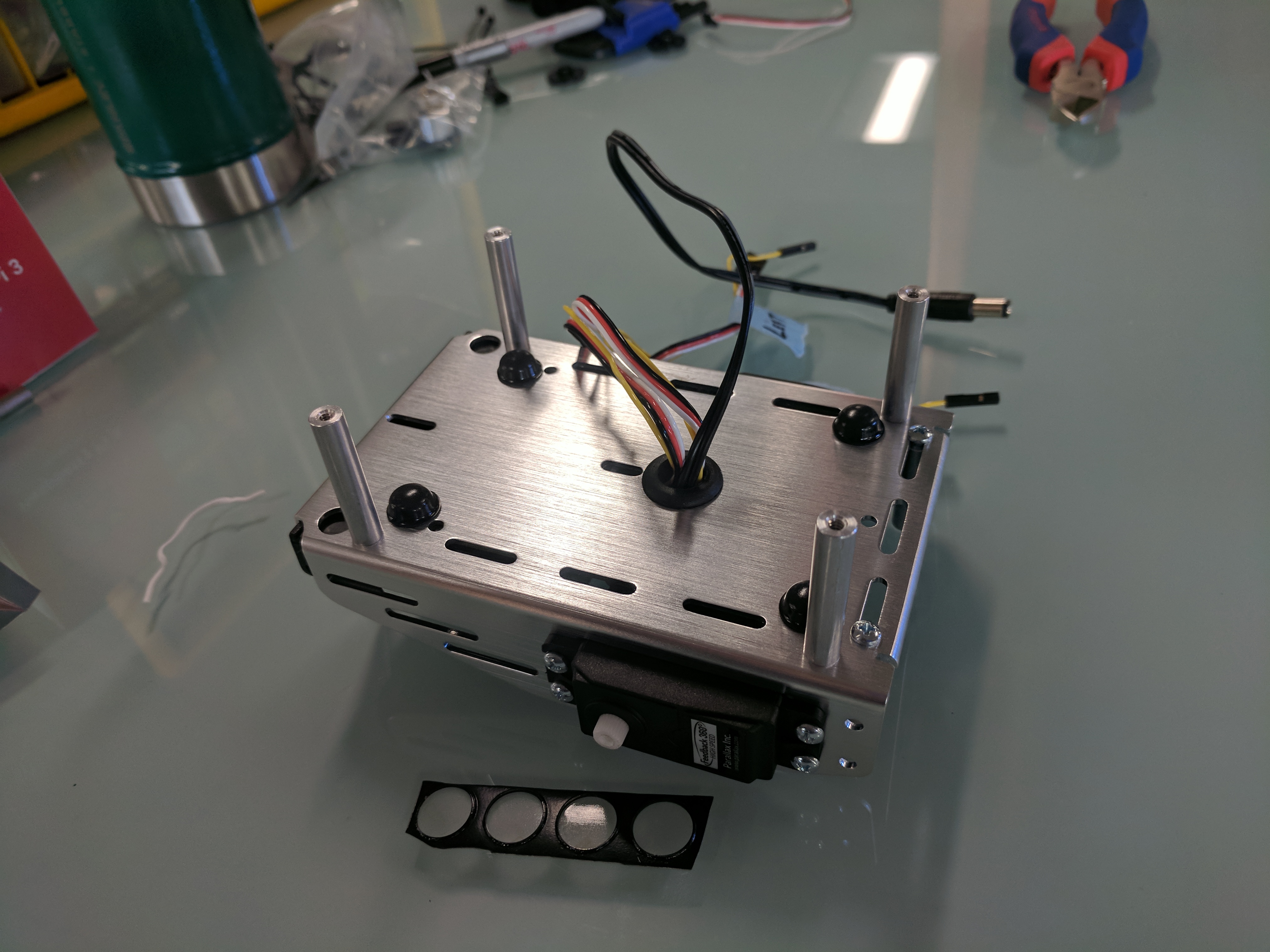
Place the four rubber feet on top of the chassis, just inside from each of the standoffs. This will provide clearance for the servo cables under the battery brick later.
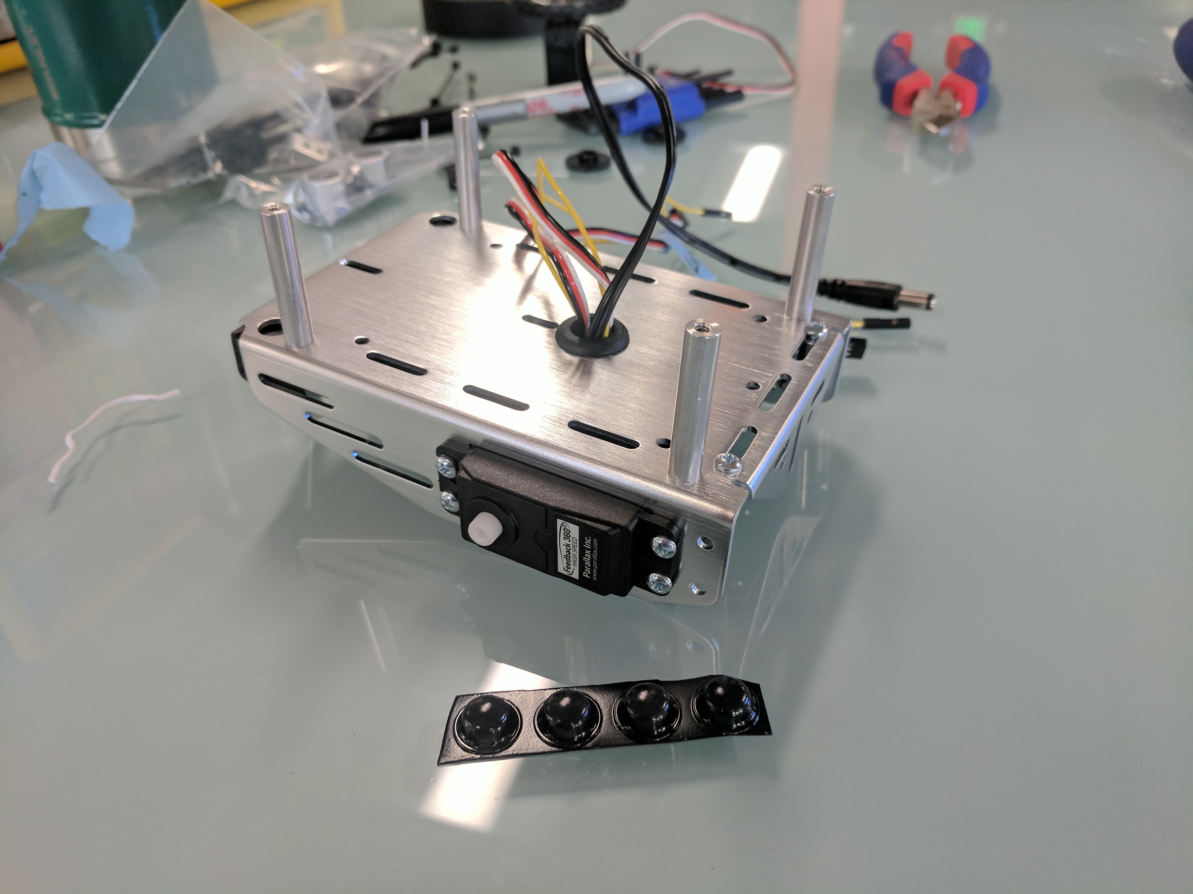
Place an o-ring tire onto each wheel.
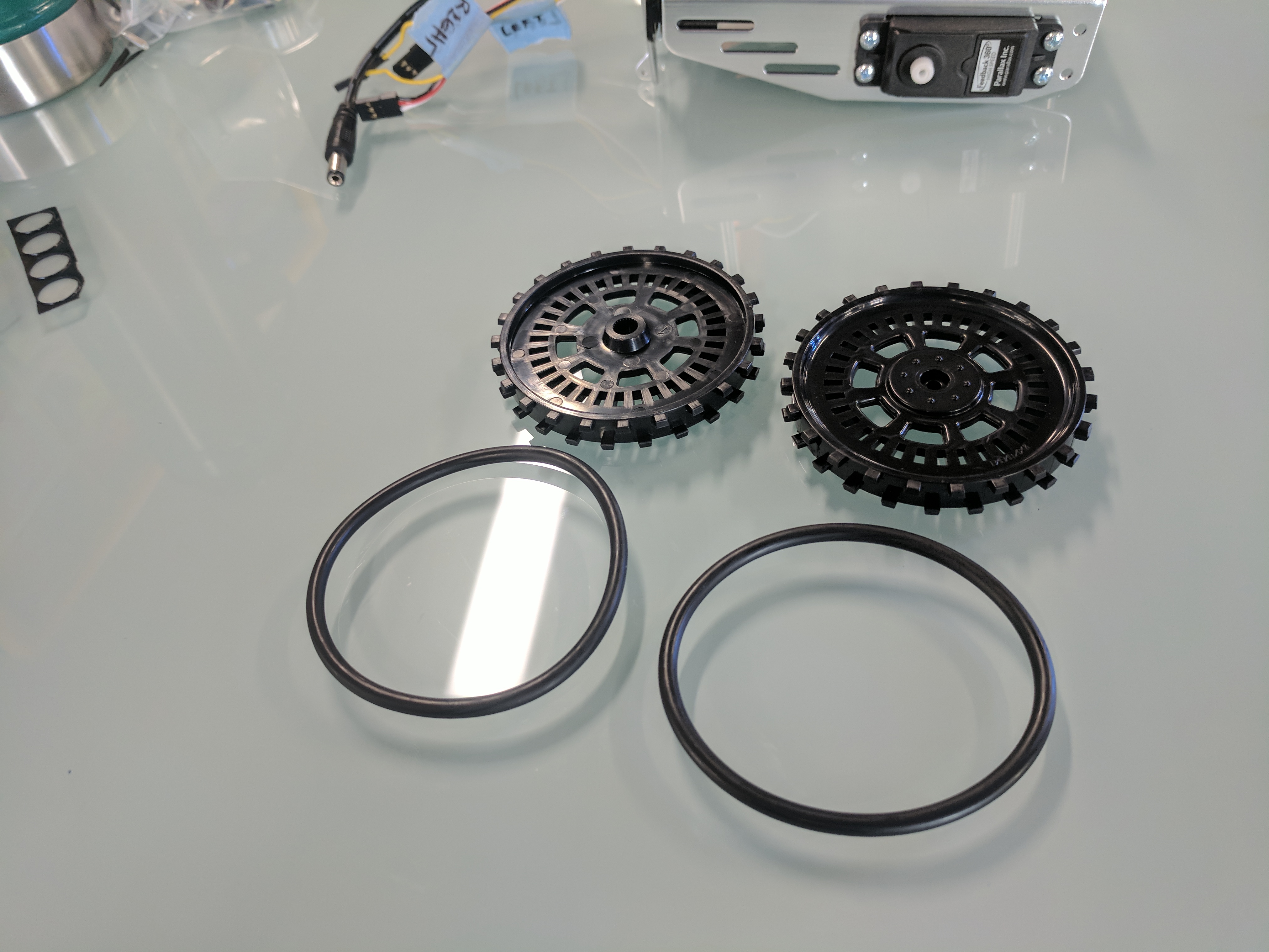
push a wheel onto each servo spline, and attach it with a reserved servo screw.
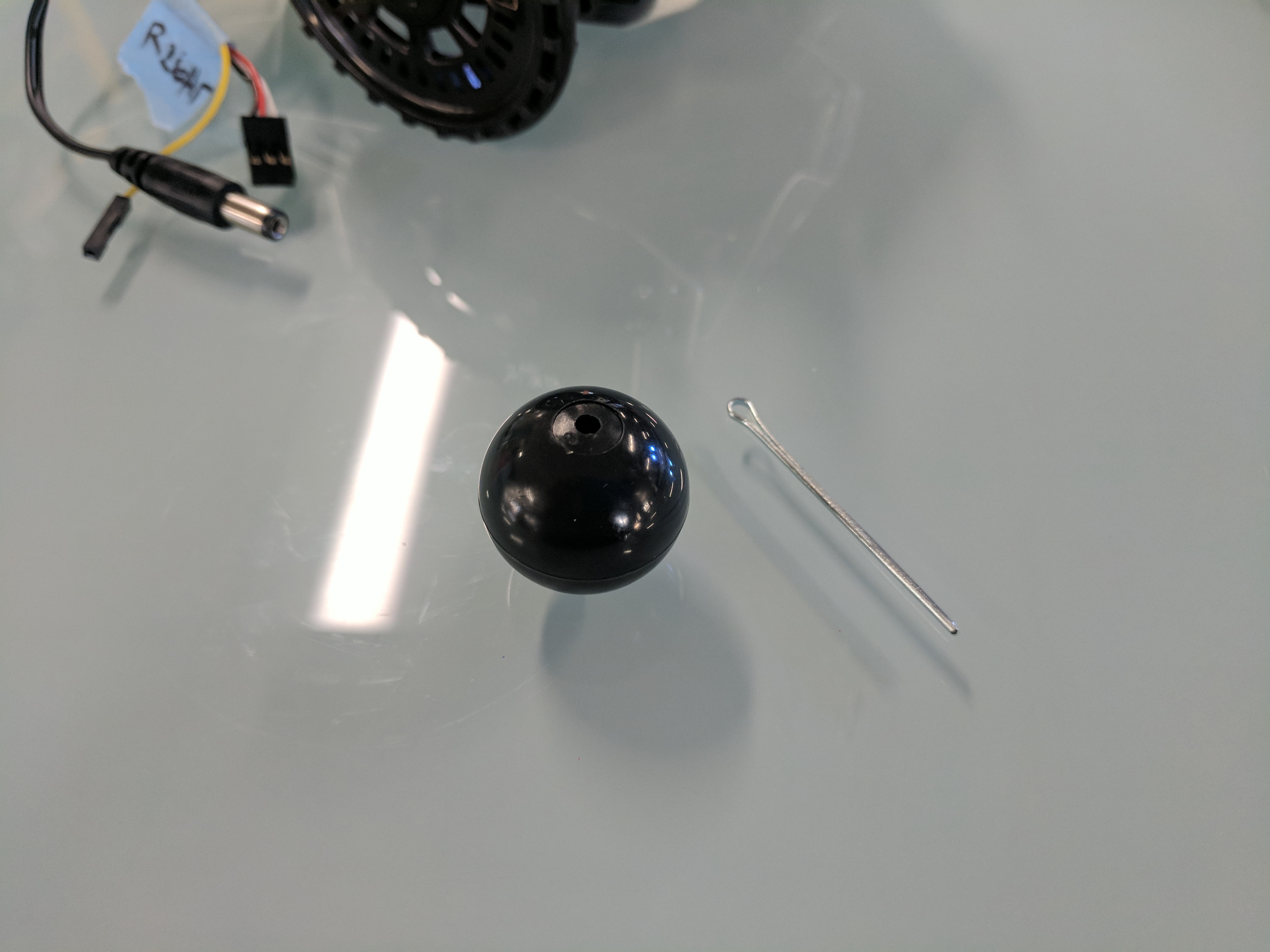
Thread the cotter pin through the side of the chassis tail mounting hole, through the tail wheel ball, and then through the opposite hole. Bend the cotter pin end to secure the tail wheel ball.
Place the Parallaxy Bottom Plate underneath the robot chassis, pressing the large rectangular area between the edges of the chassis on top of the servos.
From underneath, secure the bottom plate to the 1” standoffs using ⅜” steel screws.
From underneath the bottom plate, slip the slotted end of an ‘L’ bracket between the side of the chassis and the bottom plate.
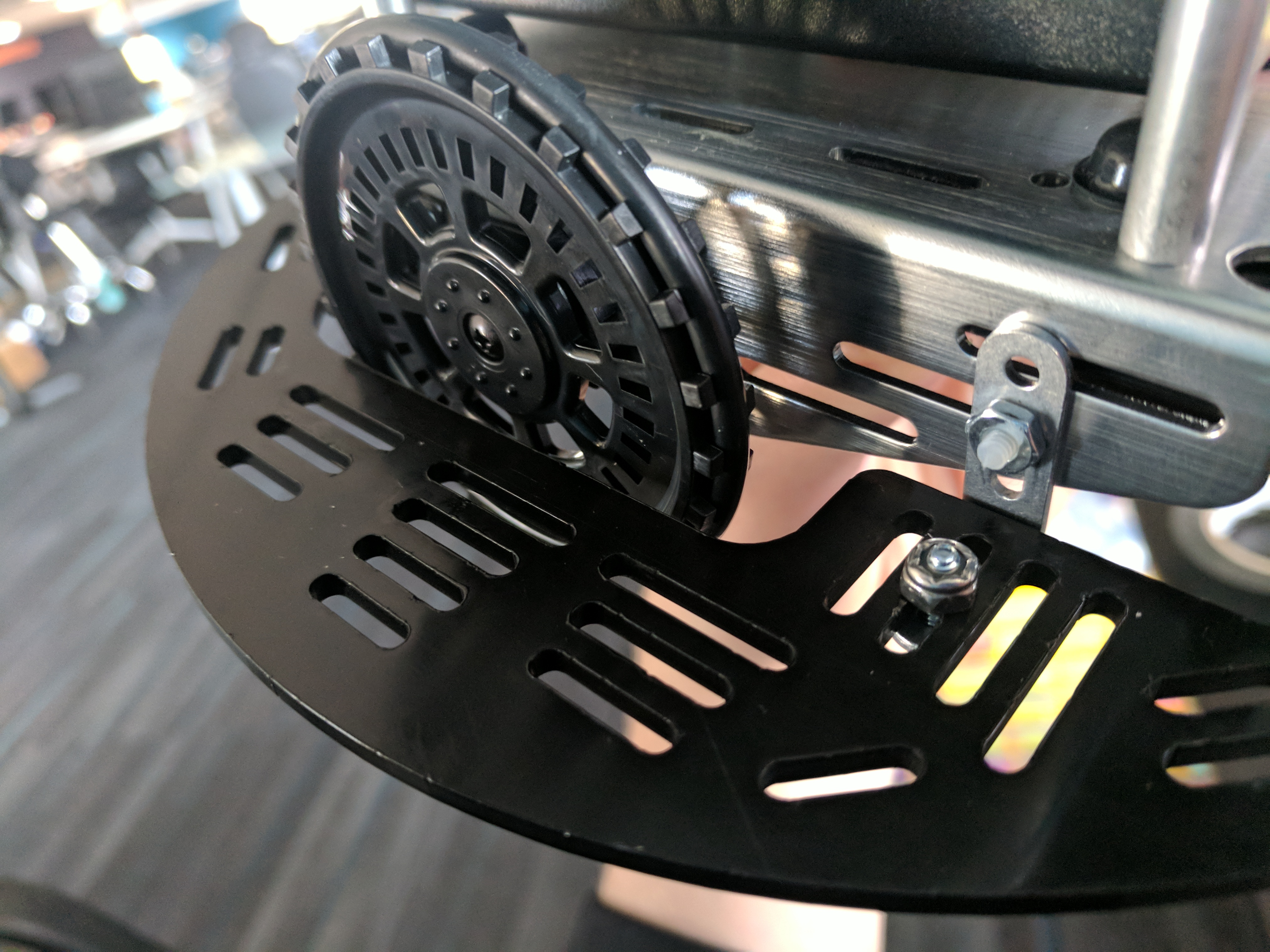
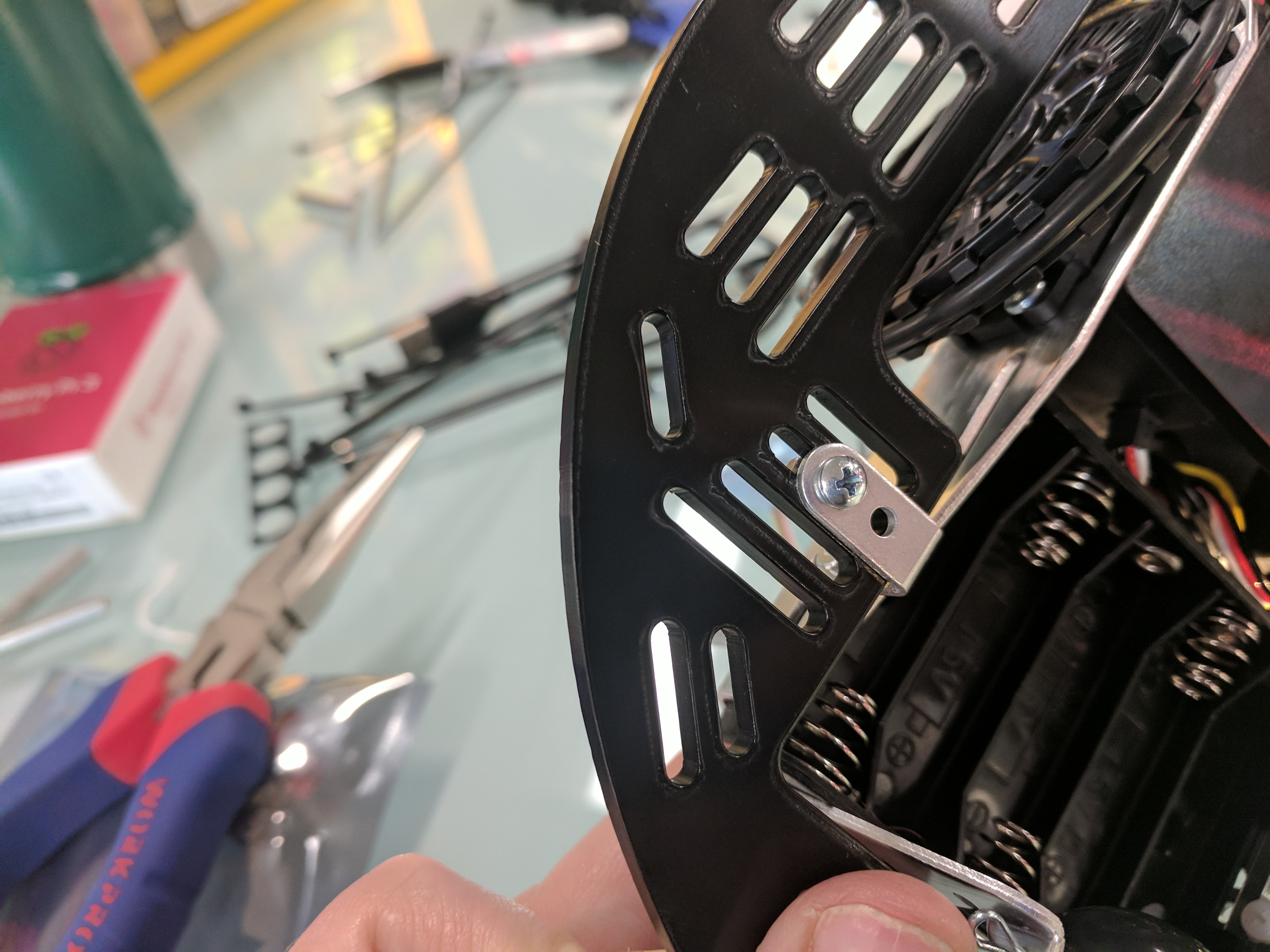
Loosly attach the ‘L’ bracket to the outer side of the chassis, behind the servo, in the chassis middle slot, using a ½” Nylon pan-head screw and a regular nut.
Slide the ‘L’ bracket towards the tail wheel until its bottom holes line up with a slot in the bottom plate, then Tighten the Nylon screw.
Insert a ⅜” steel screw from underneath the bottom plate, up through a slot, and through the outer hole in the ‘L’ bracket, and secure in place with a Nylon core lock-nut (Don’t go from the top down, because a projecting screw might get caught on something).
Repeat with the other ‘L’ bracket on the other side of the robot. The bottom plate should now be secured to the aluminum chassis at four points.
If the 5-AA battery pack is installed for future use, tuck its cable under the chassis in the pocket made by the bottom plate for now.
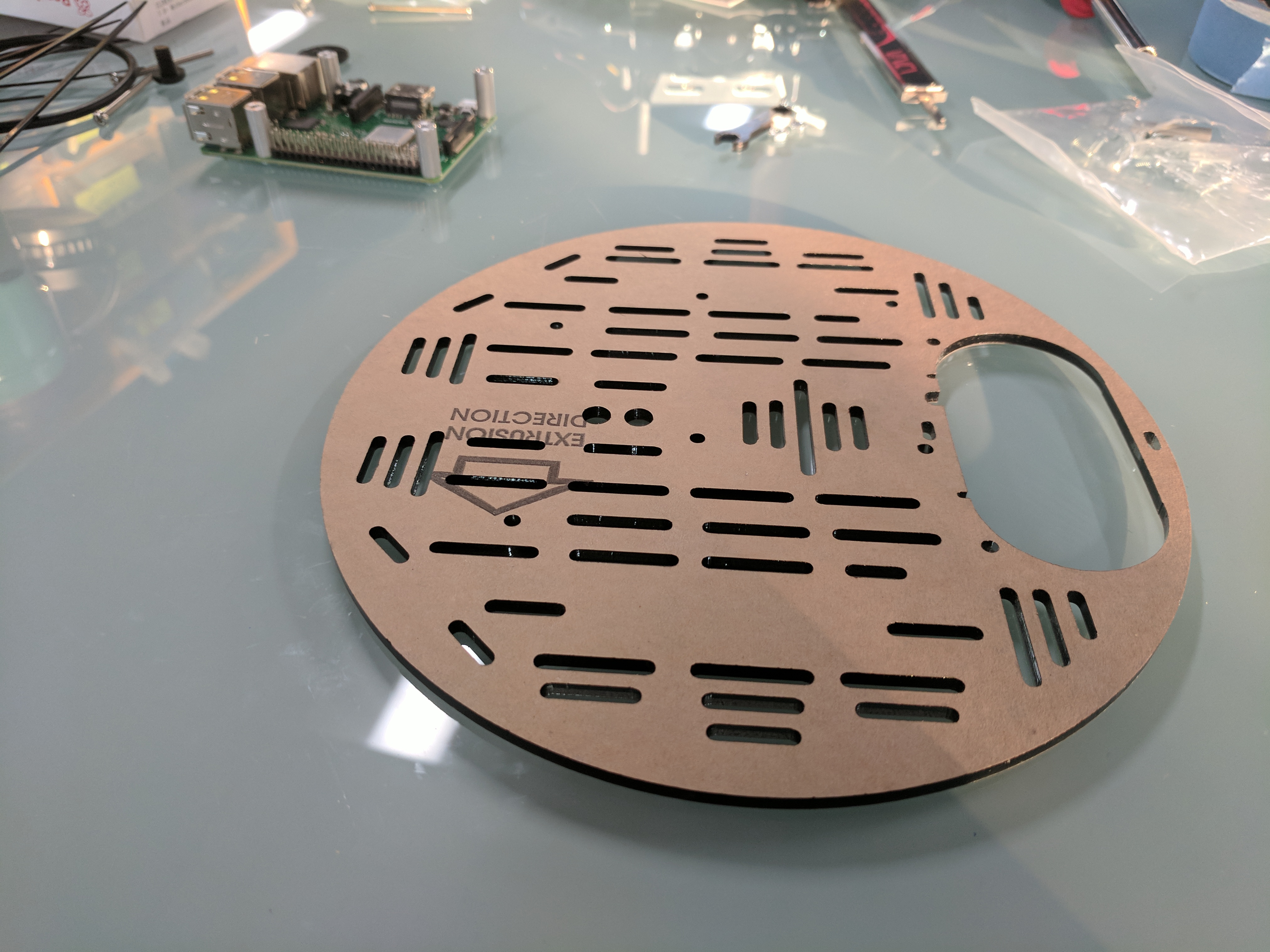
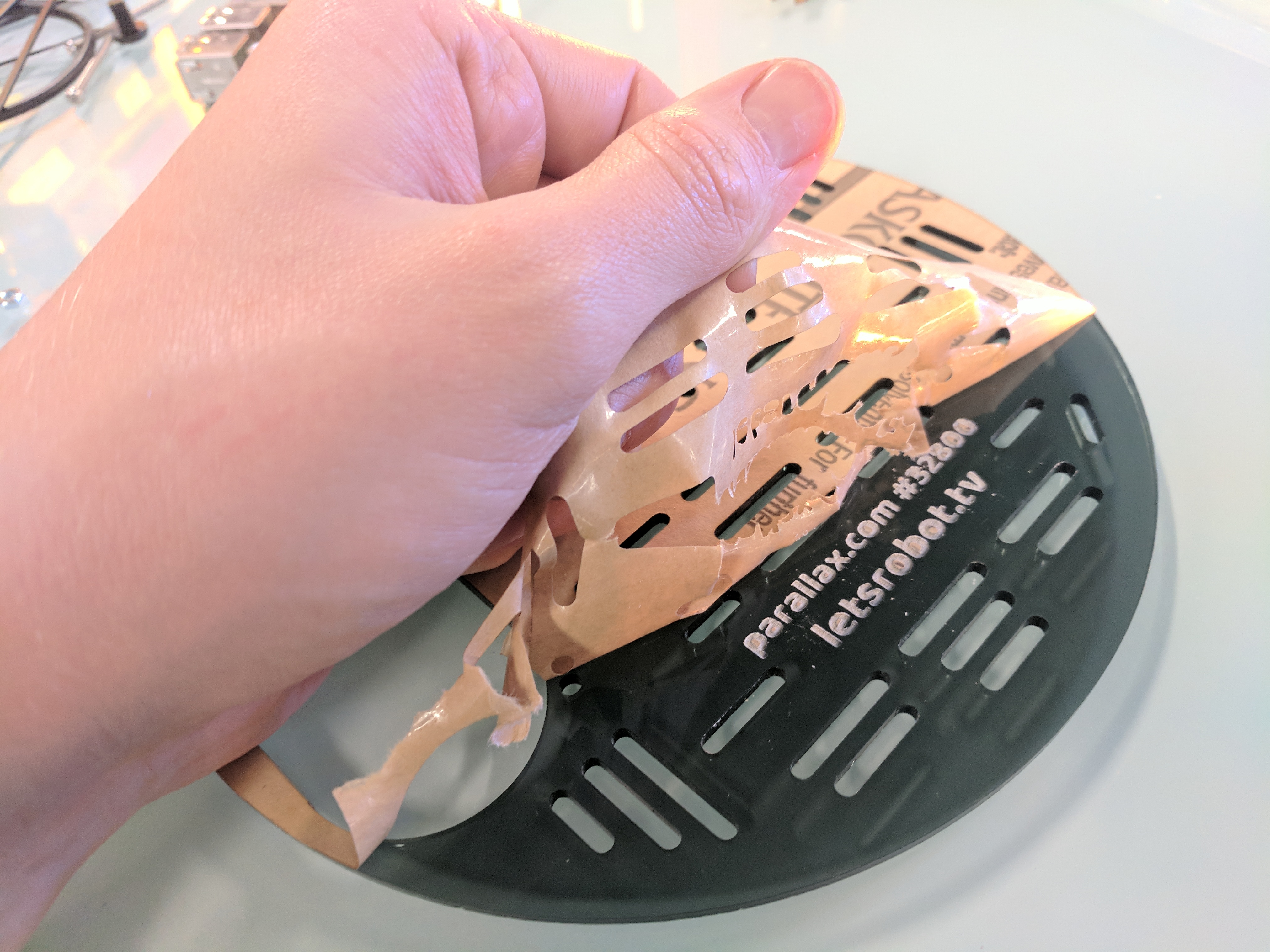
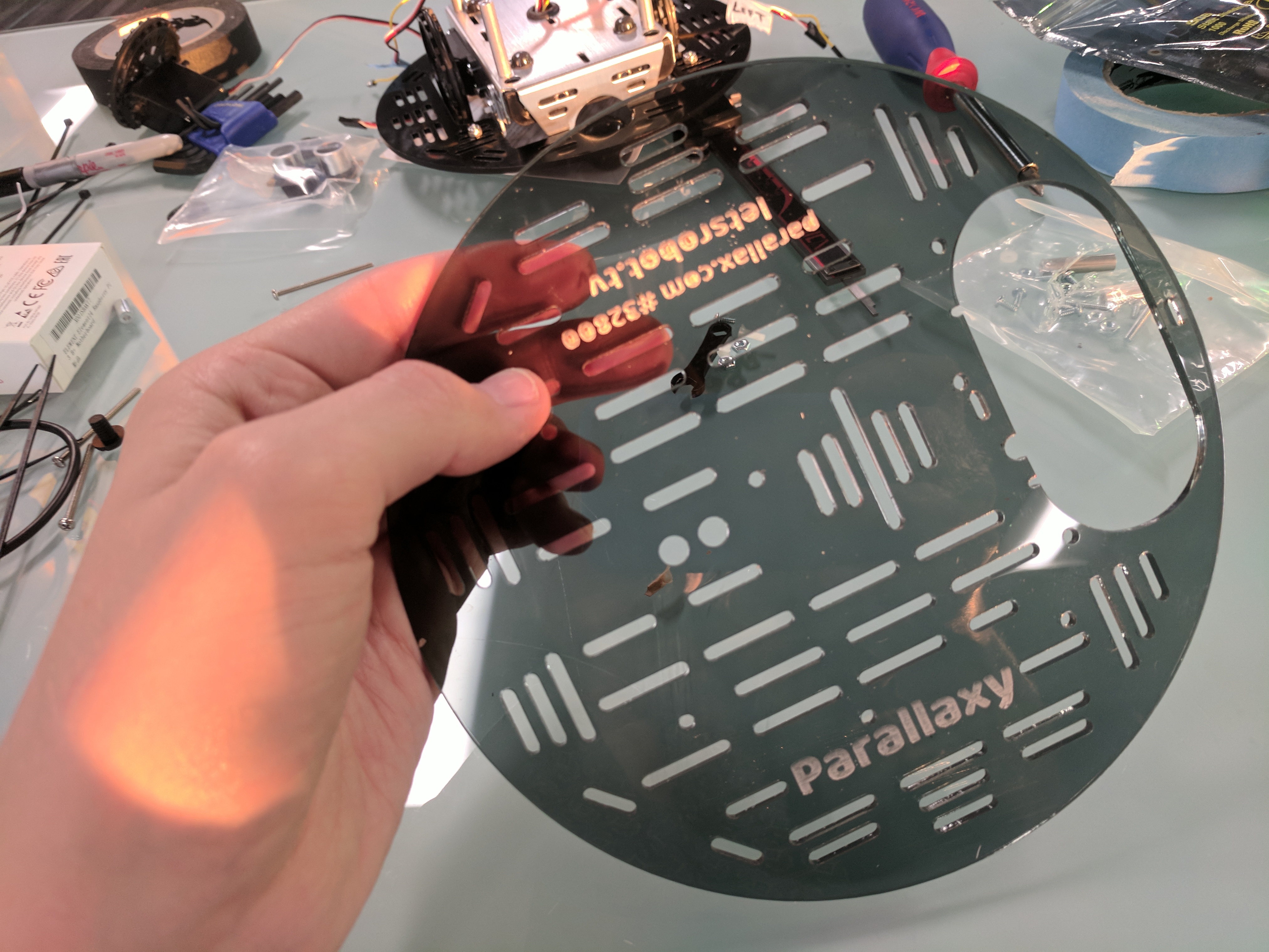
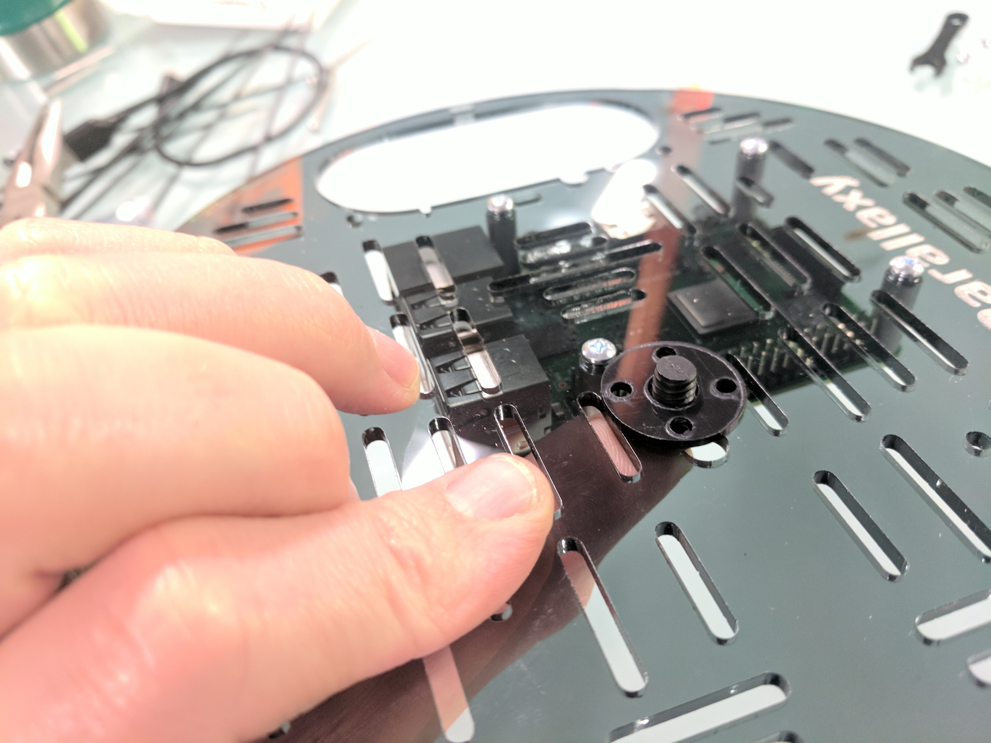
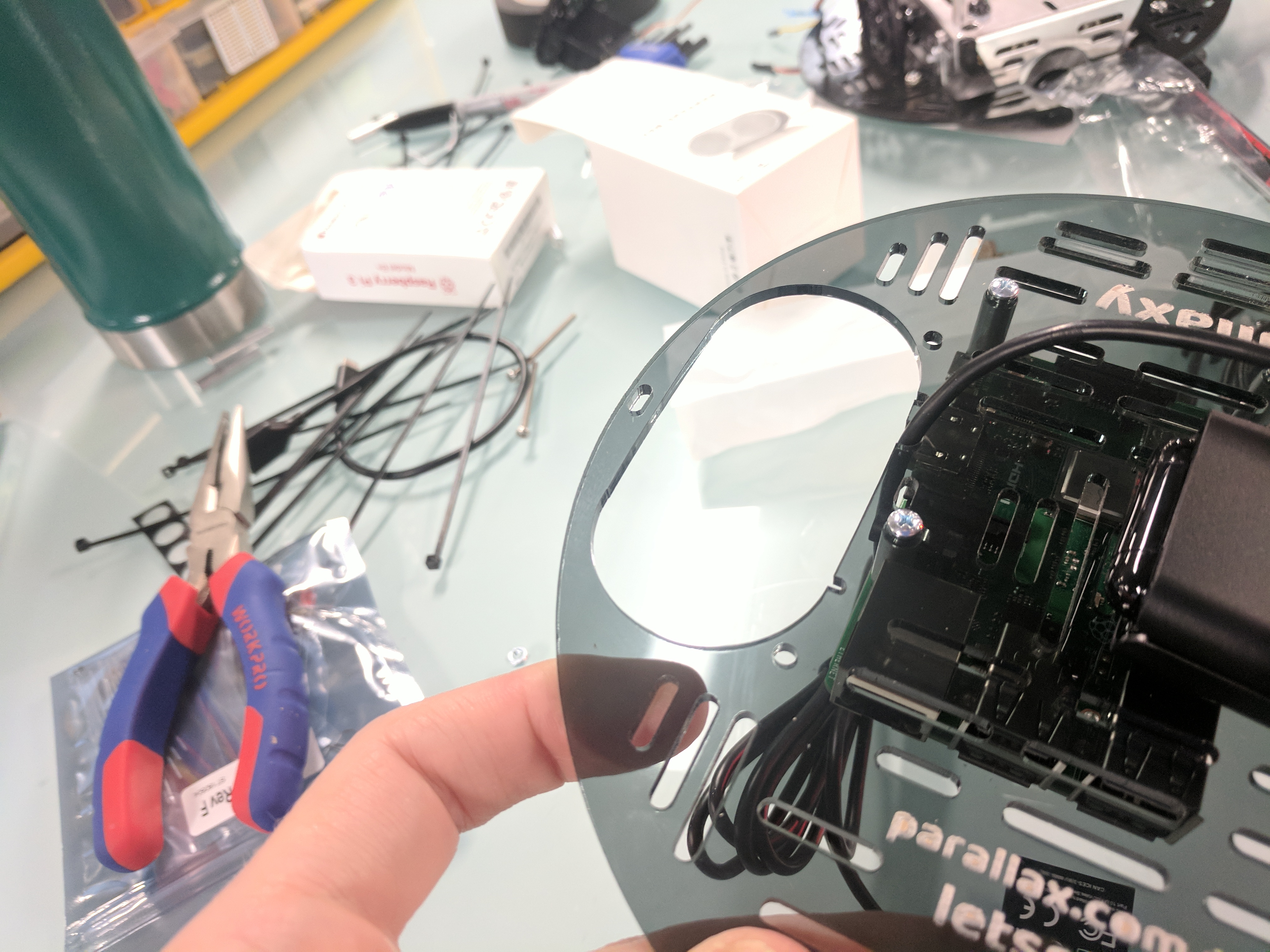
Peel paper off both sides of the Parallaxy acrylic top plate.
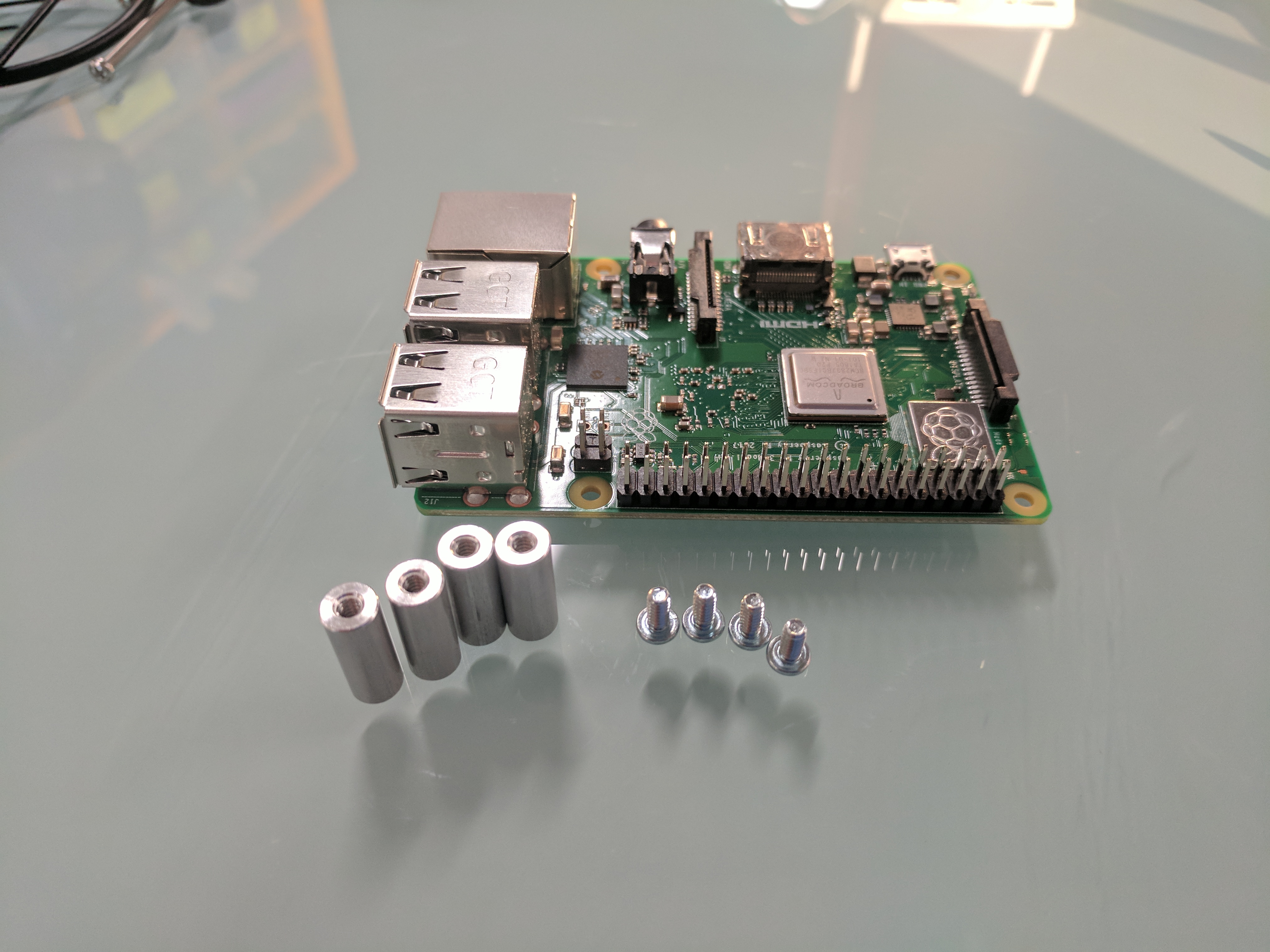
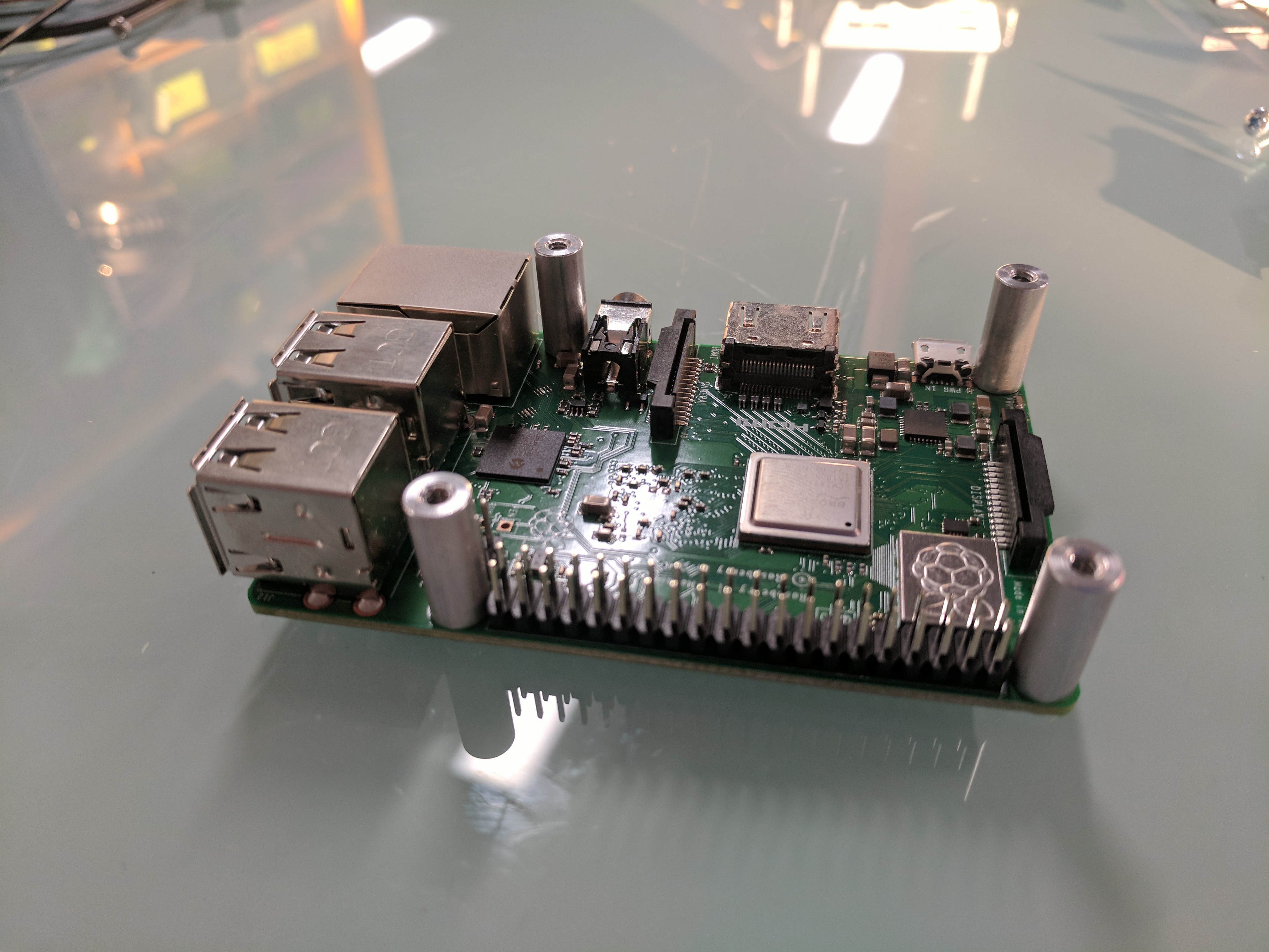
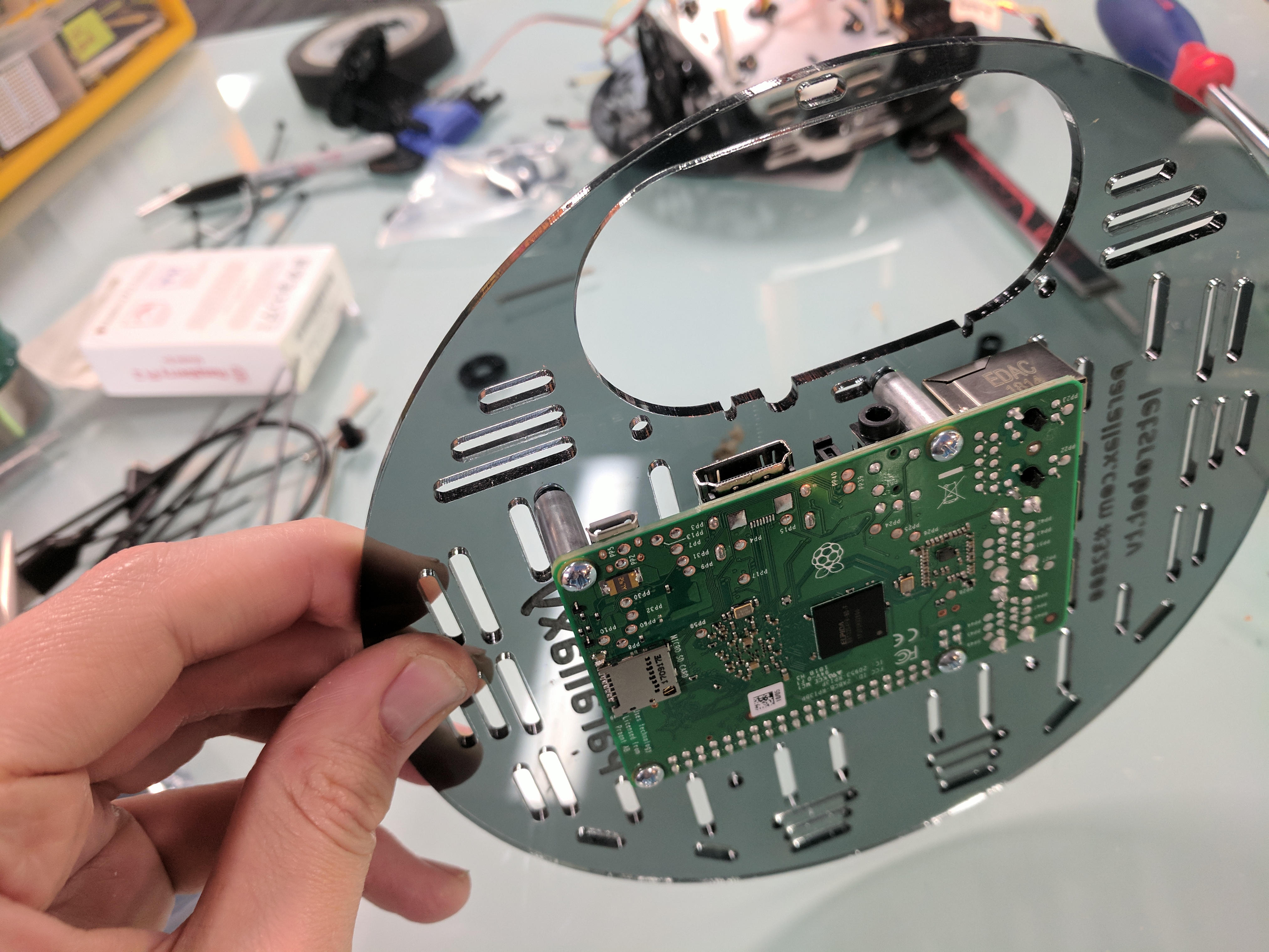
Attach four ⅝” threaded standoffs to the top of the Raspberry Pi board using ¼” steel screws.
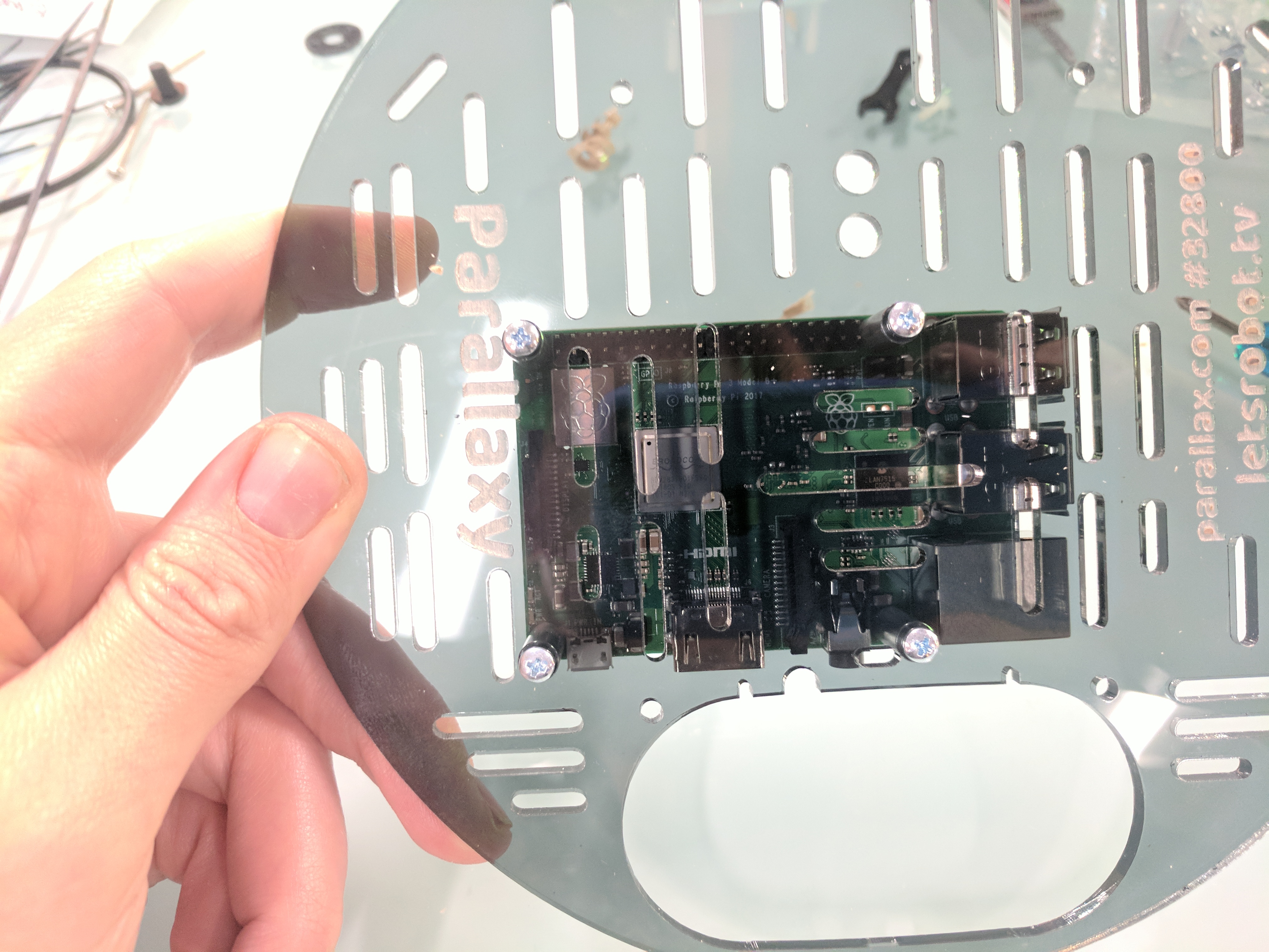
Attach the Raspberry Pi board to the underside of the top plate with four ¼” steel screws. It goes just above the large oval opening, mounted cross-wise, off-center to the left with its USB ports pointing to the right.
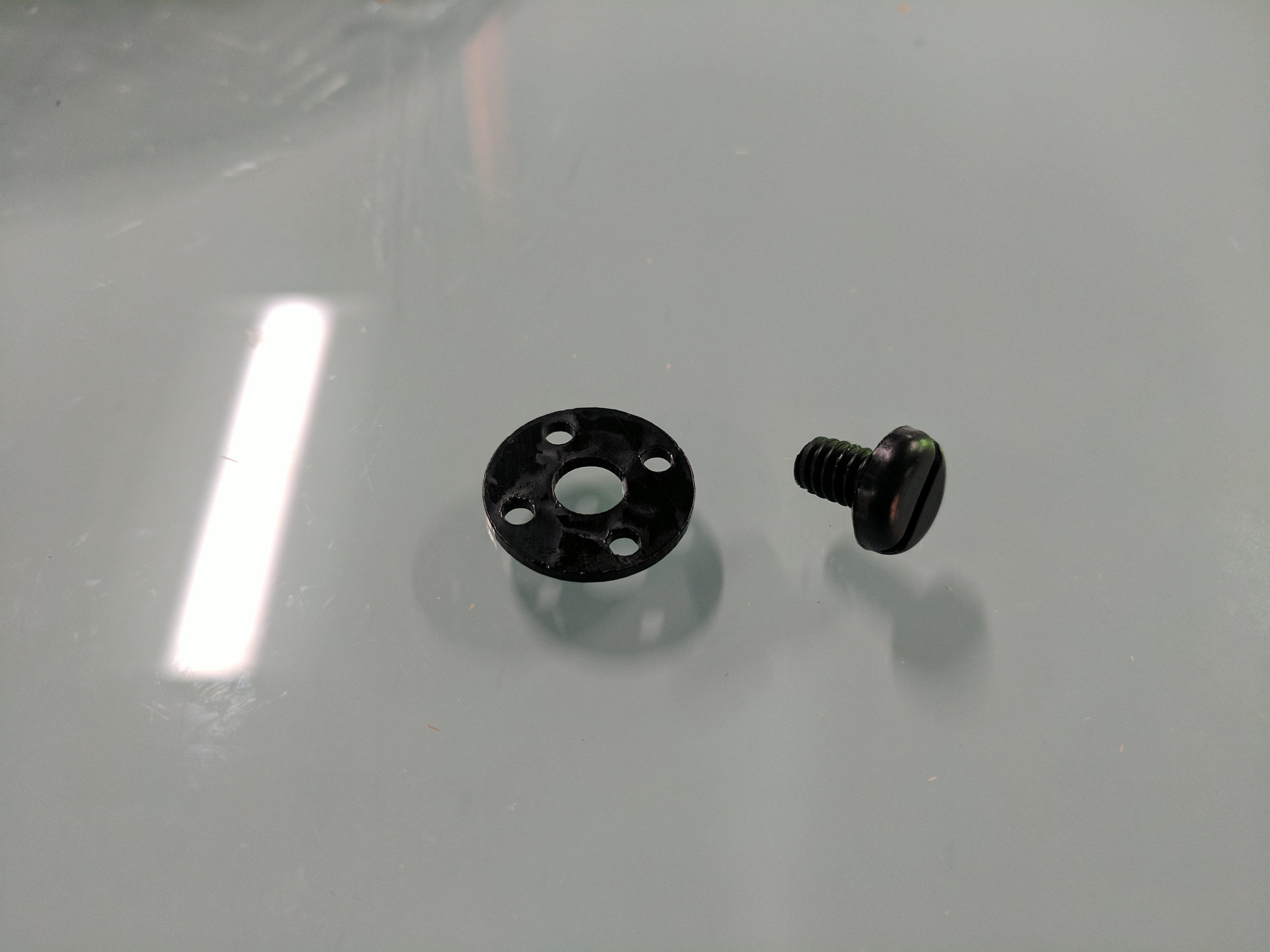
Attach the camera to the top plate in one of the two larger round holes. Use the black nylon screw from underneath the plate, and the black Delrin washer on top of the plate. The washer helps the camera foot clear a screw head holding the Raspberry Pi in place.
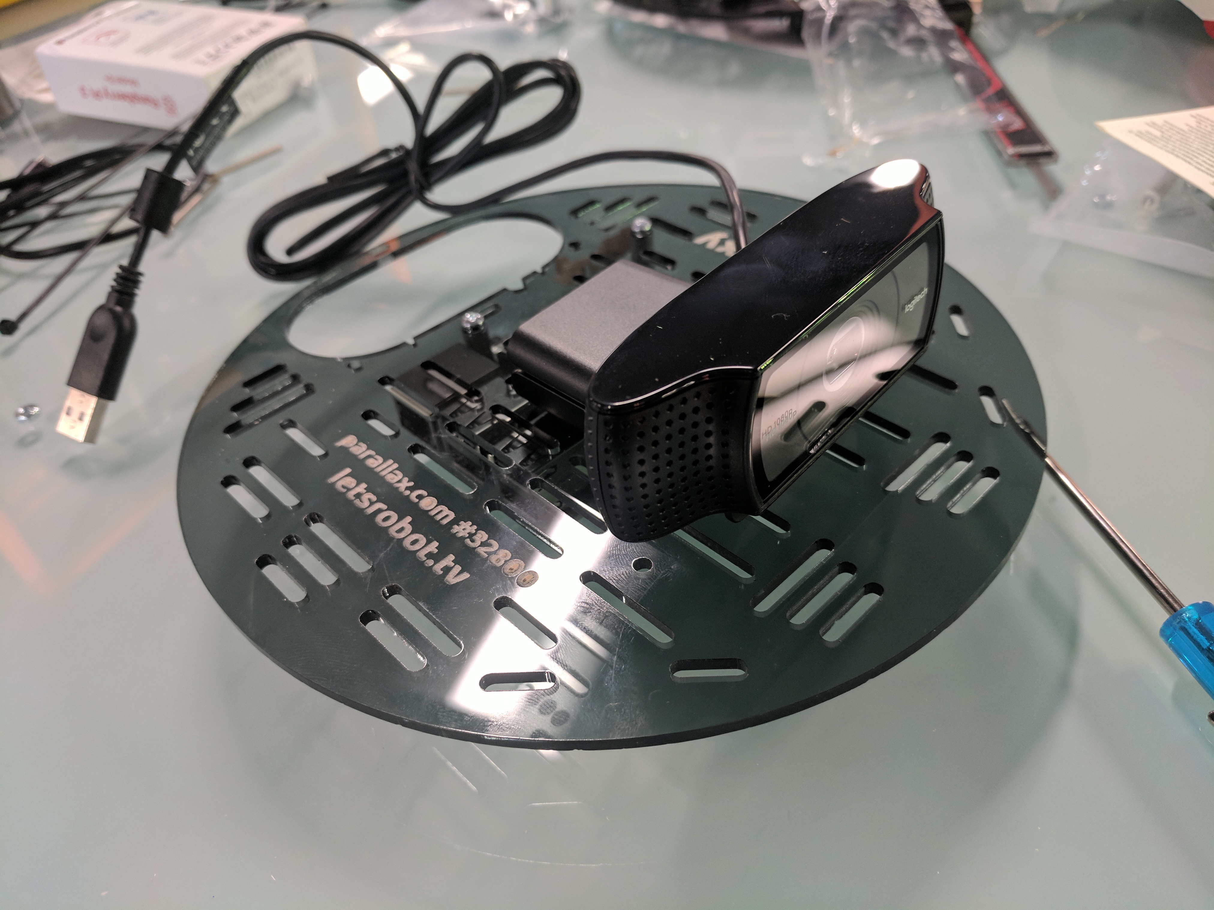
Thread the camera through the large oval hole, with its cord resting in the half-circle notch.
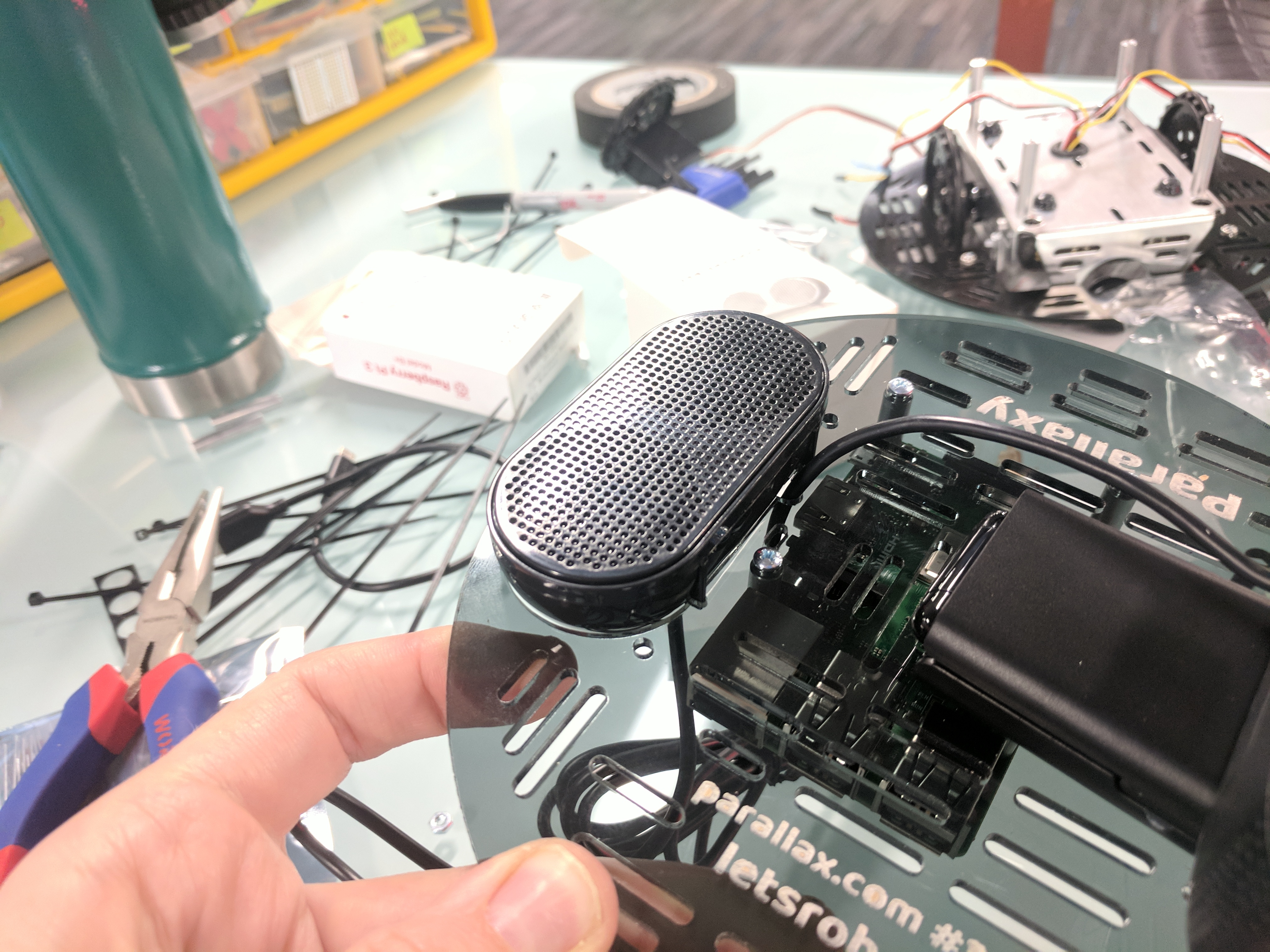
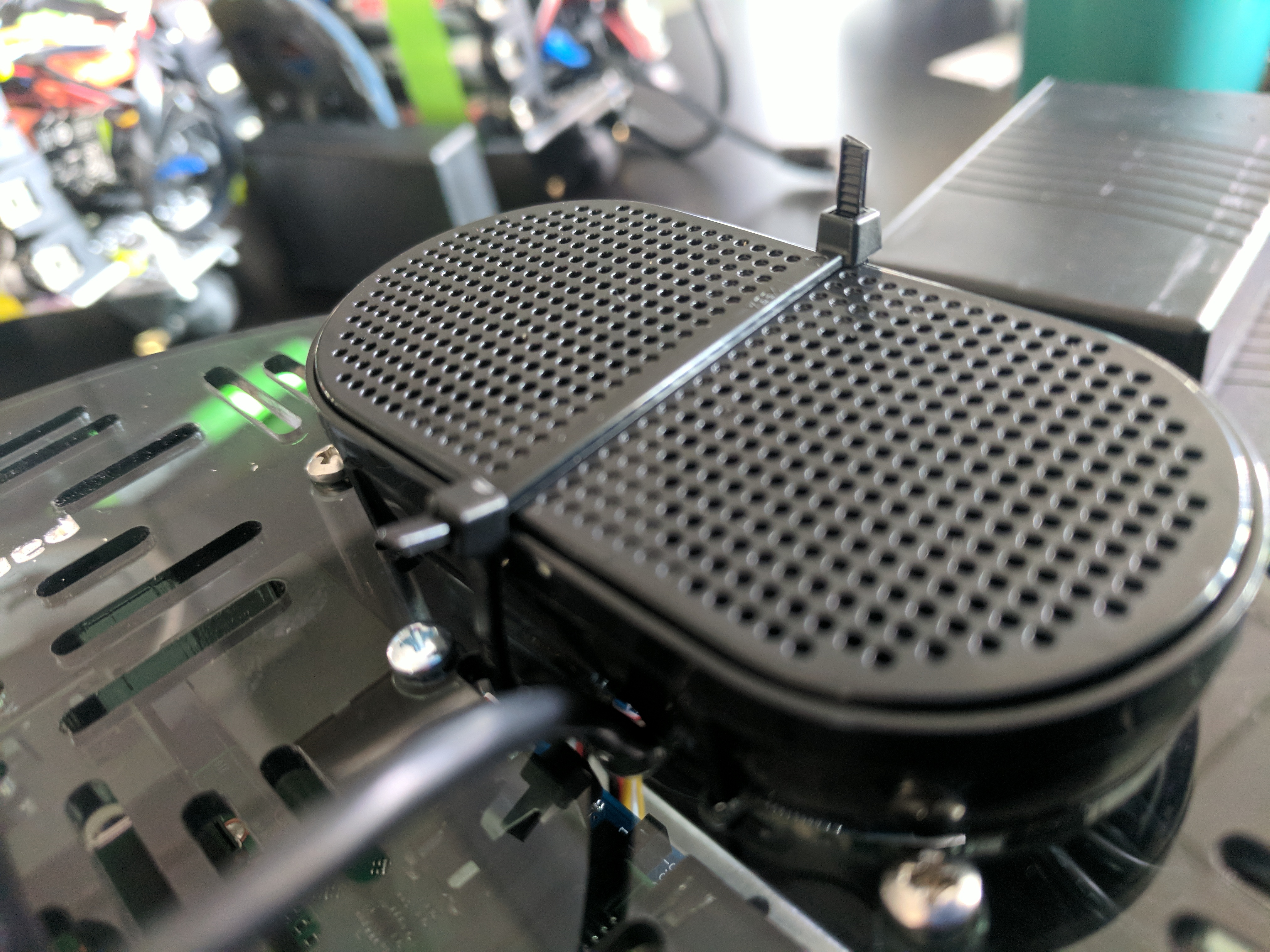
Place the speaker so that it’s cradled in the top plates large oval hole. Its tiny two legs fit into the two notches. Secure the speaker in place with a large pair of zip ties laced through the slots centered above and below the oval, and then laced through each other.
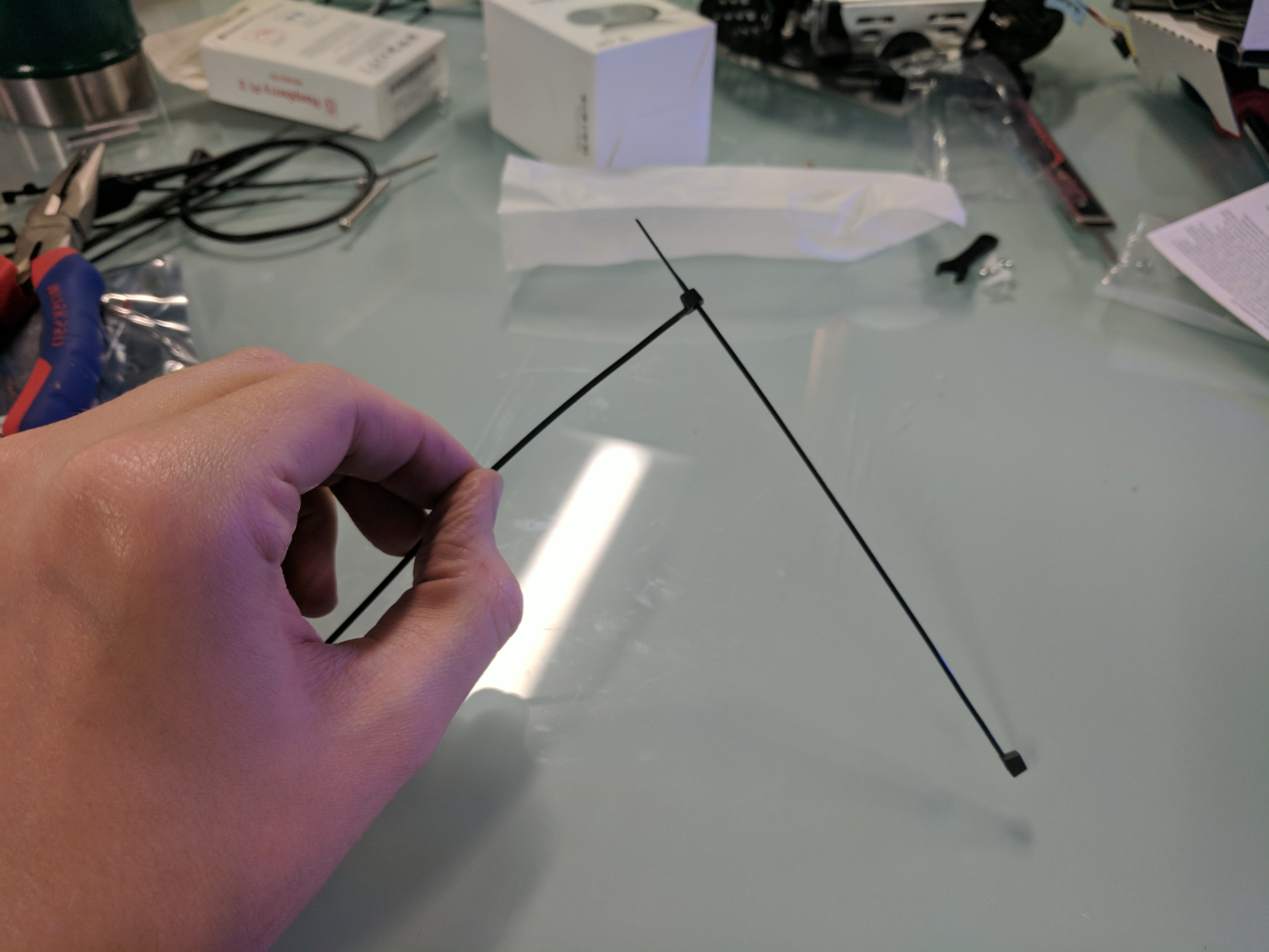
Tip
If you have not flashed your Raspberry Pi yet, zip tie the speaker in place later. If you will be flashing the Raspberry Pi frequently, consider using elastic instead of zip ties.
Place the chassis upright on a table.
Place the Activity Board WX on top of the four upright standoffs, with its white breadboard facing away from the tail wheel and its mounting holes lined up with the standoffs.
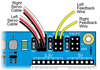
Plug the servo wires and cables into the Activity Board servo ports. You can do this now while the board is easy to access, but there is room to do it later if you need to; they are not yet plugged in for the pictures after this step.
P12- Left servo 3-pin acble, white wire to signal pin.P13- Right servo 3-pin cable, white wire to signal pin.P14- Left servo yellow feedback wire to signal pin.P15- Right servo yellow feedback wire to signal pin.
Tip
Get a friend to help you with the next steps if you can.
Flip up the camera on its mount to access the small holes in the top plate.
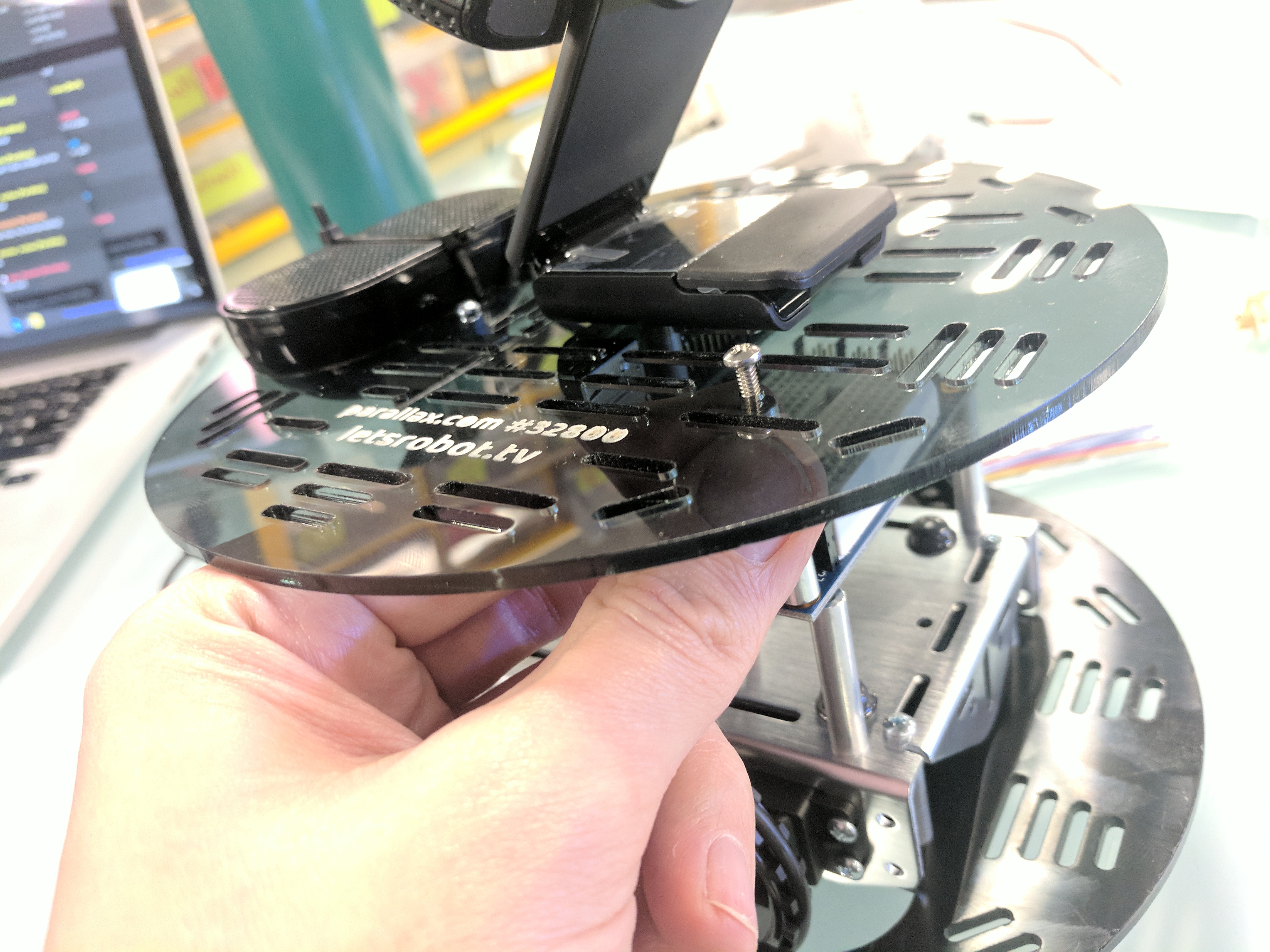
Hold the top plate cover over the chassis with the camera facing away from the tail wheel.
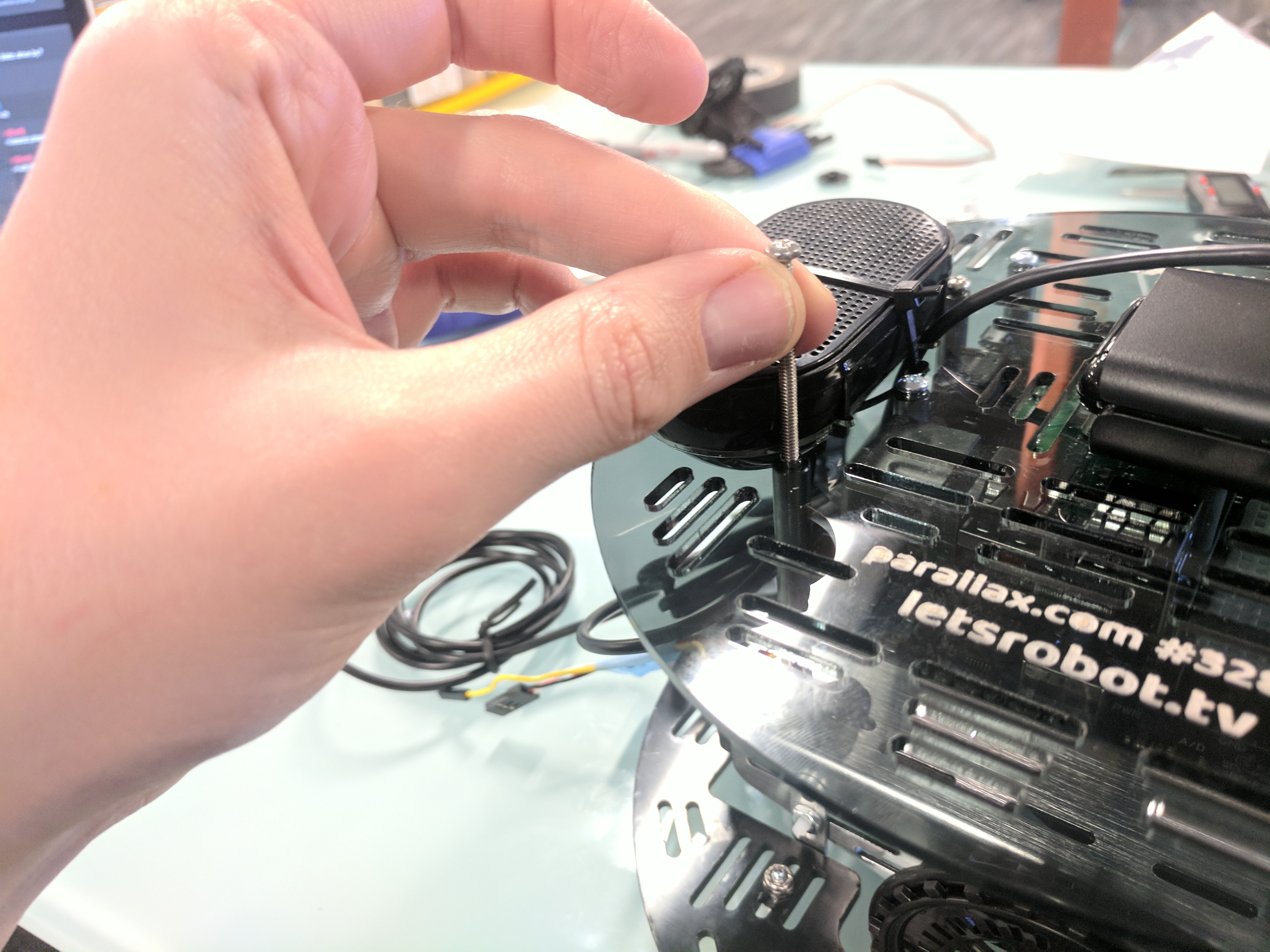
Drop a 1 ¾” screw through the top plate in one of the remaining mounting holes.
Slip a 1 ¼” spacer over the screw.
Position the spacer and screw over the corresponding mounting hole in the Activity Board WX, thread it into the standoff beneath, and tighten in place.
Repeat with the other three mounting holes until the tip plate is firmly attached to the bottom plate.
Tip
If you have not flashed your Raspberry Pi yet, or expect to be doing so frequently, leave out the rear standoff to the left of the tail wheel. It will make accessing the HDMI port easier.
Gently pull the servo’s cables towards the left servo.
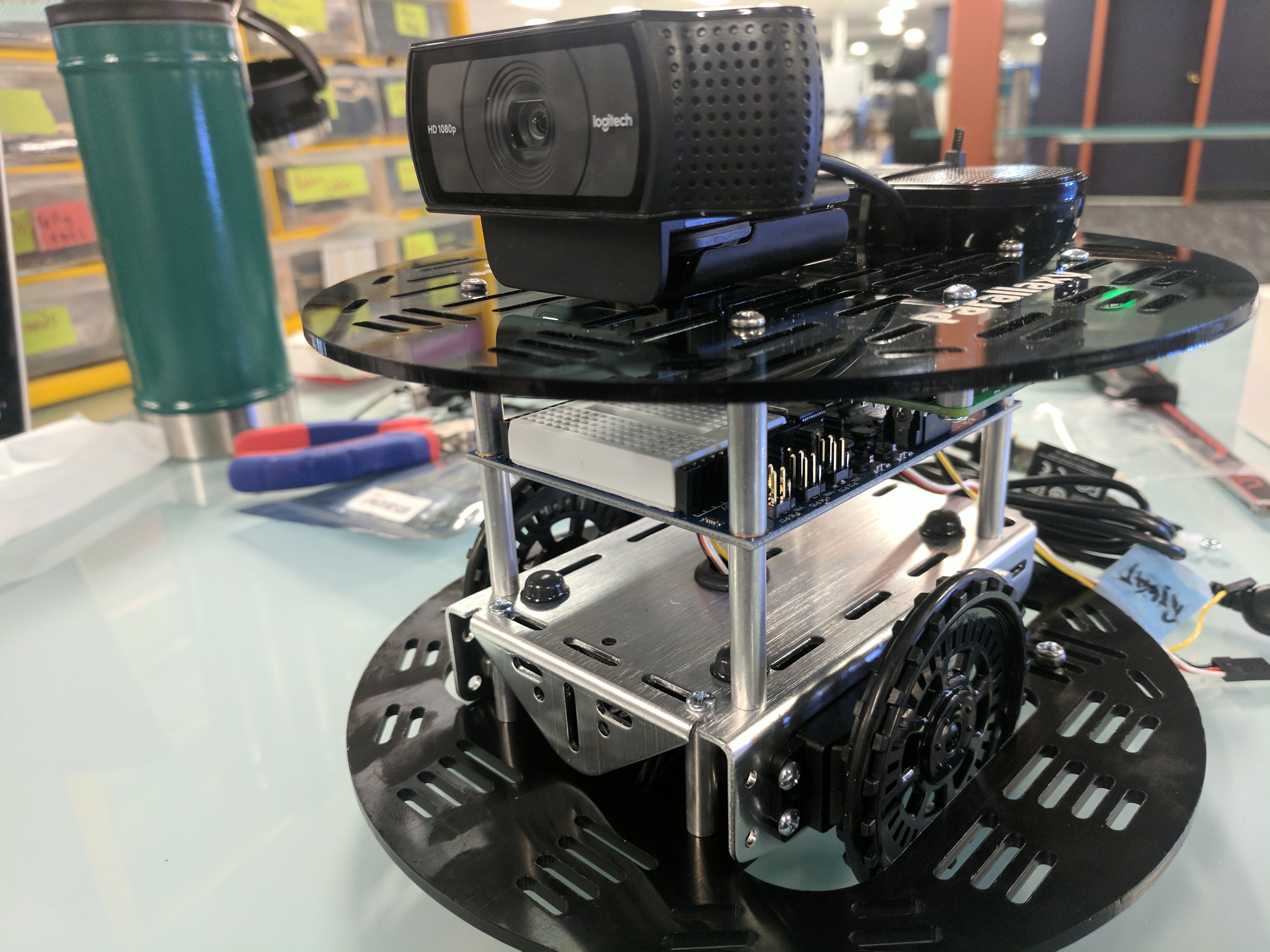
Slide the battery brick underneath the Activity Board WX, so its power switch is towards the tail wheel.
ZOMG!1! You’re done with the main assembly! Huzzah!
Parallaxy Connections
Activity Board WX Double-Check
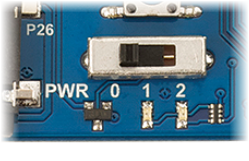
If you have not done so already, make sure the 3-position power switch on the Activity Board WX is set to Position 0 (off).
If you have not done so already, make sure all Activity Board WX servo port jumpers are set to
5Vand if not, move them.
- If you have not done so already, make the following servo port connections.
P12- Left Servo 3-pin cable, white wire to signal pinP13- Right Servo 3-pin cable, white wire to signal pinP14- Left servo yellow feedback wire to signal pinP15- Right servo yellow feedback wire to signal pin
Battery Brick connection for Activity Board WX Programming
- Make sure the power switch on the battery is in the OFF position.
- Plug one end of the battery brick’s barrel cable into the jack on the Activity Board WX (yes, it will flex just enough around the standoff).
- Plug the other end into the round jack on the battery brick.
Cable Management
Coil up and secure the webcam cable with zip ties.
If your Raspberry Pi is already flashed and ready to use, go ahead and secure the speaker in its cradle with zip ties, then coil and secure its cable. If not, wait a bit!
Tip
If you will want ongoing HDMI port access, secure the speaker in its cradel with elastic instead of zip ties.
Don’t connect or zip tie the USB A to Mini B cable yet - it is needed for programming the Activity Board WX.
Helpful Tips
- Tight flat bundles that fit vertically between the top and bottom plates work well.
- Keep the weight of the cables as far towards the back as possible to balance out the weight of the webcam.
- Don’t block access to the power switches on the Activity Board WX or the battery brick.
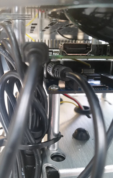
- Try not to block access to the HDMI port or SD card slots. You can remove and leave off the left rear standoff if you want frequent easy access to the HDMI port.
- If you keep the cables within the diameter of the top plate, you can attach a cylindrical skirt around the outer edge of the top plate and it will rest on the slightly larger diameter bottom plate to hide the innards once everything is all done.
Parallaxy Software
Parallaxy Checklist
In this seciton, we are adding all the software needed to run Parallaxy in the following steps:
- Calibrate your robot using BlocklyProp
- Flash the Propeller firmware on the Activity Board WX using BlocklyProp.
Parallaxy Calibration
Robot Calibration and Propeller Firmware
Before connecting to the Raspberry Pi, the Activity Board WX needs to be programmed directly from your computer for two purposes: First to calibrate the robot for its weight and power supply voltage, and then to load the Parallaxy firmware.
Get setup for BlocklyProp Programming
Follow the Getting Started with BlocklyProp Guide to create a free account and test your connection. Installation of a small client program and FTDI drivers is needed.
Calibration
The calibration code takes about one minute to collect all of its data. You will
need a smooth and obstacle-free floor area. While the calibration program is
running, Parallaxy will pivot forward and backward, using only one wheel at a
time. It will let you know when it is done by turning off its P26 and P27
lights (below the breadboard). Here’s a video showing an Activity Bot 360
correctly performing the calibration maneuvers.
Attention
Make sure your battery brick is charged before calibrating!
Log in to your BlocklyProp account, and run and connect the BlocklyProp client on your computer.
Turn on power at the battery brick switch.
Set the Activity Board WX power swtich to 1 (this powers most of the board but not the servo headers, so it doesn’t roll off the table when you download).
Connect the Activity Board WX to your computer via the USB A to Mini B cable.
Start a new project for the Activity Board.
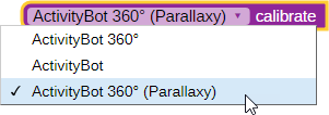
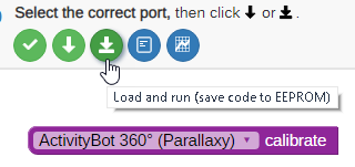
From the ROBOT block menu, place the ActivityBot calibrate block into the workspace, and choose ActivityBot 360 (Parallaxy) from the drop-down menu.
Click the Load and Run button.
When the program is finished loading, the
P26andP27lights will turn on, turn off the robots power (slide the switch to 0).Disconnect the Parallaxy from its programming cable and set it on a 1-meter (approx. 3’x3’), obstacle free, smooth floor area.
Set the power switch to 2 and move back to give it room to spin in place and slowly roam while it gathers wheel speed data.
Leave it alone until the
P26andP27lights turn off. After that, calibration is complete and you can turn the power off again.Attention
If your Parallaxy shook its tail wheel at the end, calibration has failed!
Checking Calibration Results
There is a block that can check the calibration data and tell you if there are any mistakes or problems with Parallaxy’s current servo, encoder, or power connections. If this test says the calibration was successful, your Parallaxy will be ready for its firmware. If not, then it will tell you what problem(s) it detects. After finding and fixing the problem, make sure to run both the calibration and this test again. Your Parallaxy will not be ready for firmware until it is calibrated AND passes this test!
Set the Activity Board WX power switch to 0 and reconnect the USB cable.
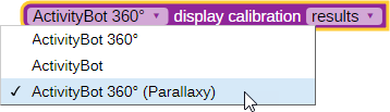
Replace the Calibrate block with the Display calibration block. Set its drop-down menus to ActivityBot 360 (Parallaxy) and results as shown below.
Set the power switch back to 1, then click Load and run (save to EEPROM) button again.
Terminal
What if it didn’t work?
If the results in the terminal say “…. one or more problems were detected” it means that there is probably a mistake in the servo, encoder, or power connections. Make a note of the details that the terminal reported. Then, re-check your existing electrical connections to power, servo header voltage jumper, and to the servo’s cables and feedback wires.
What if I need to restart or repeat the calibration?
To restart the calibration process, push the reset button any time while the
P26 and P27 lights are on. To repeat the calibration process once it has
fully completed, you will need to use BlocklyProp to reload the program. That is
because the program modifies itself at the end so that it cannot run a second time,
which keeps your Parallaxy from trying to recalibrate the next time you turn
power on to load a new program.
Parallaxy Firmware
Load the Propeller Firmware
- Put the Activity Board WX power switch back to position 1
- Reconnect the robot to the computer with the USB cable
- From the ROBOT block menu, place the Load Robot Firmware block in the workspace and choose ActivityBot 360 (Parallaxy) from the dropdown menu.
- Click the load and run button
- Once the download is completed, turn off power on the Activity Board.
- Turn off power at the battery brick.
Complete the Electrical Connections & Cable Management
- Keep the Mini B end of the USB cable in the Activity Board’s programming port
- Plug the A end of the USB cable into a Raspberry Pi port.
- Plug the 1 ft USB A to Micro B cable’s A end into the USB port of the battery brick
- Plug the other end of the Micro B port on the Raspberry Pi
- Secure the remaining cables with more zip ties, keeping access to the power switches and staying clear of the drive wheels.